Manual, Control Module, PROFINET, DL10
Document #9620-20-C-DL10-04
Pinnacle Park • 1031 Goodworth Drive • Apex, NC 27539 • Tel: 919.772.0115 • Fax: 919.772.8259 • www.ati-ia.com
C-34
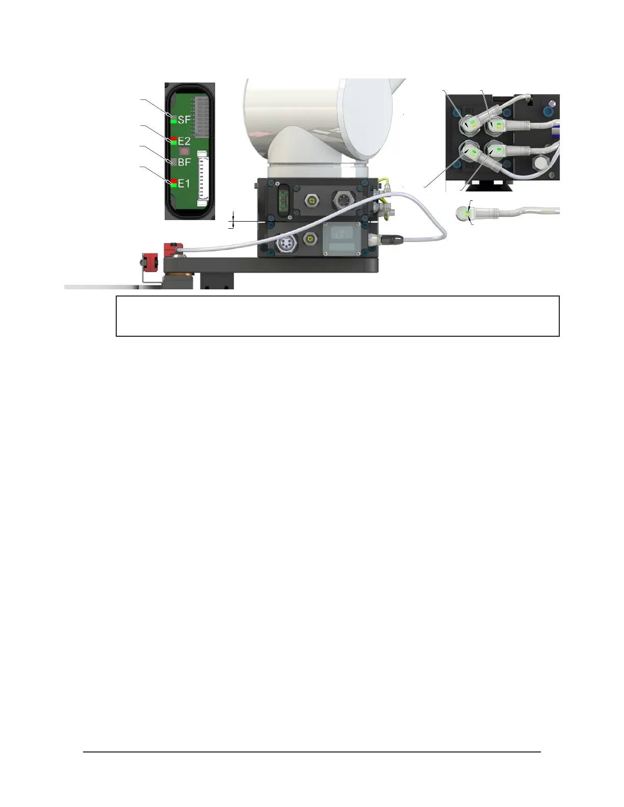
Figure 4.4—Master Moves into Tool and is parallel at 0.06”
RTL (R1)
Unlock (U)
RTL (R2)
Lock (L)
Green LED (Power)
Yellow LED
(Switch Made)
0.06" Away
SF LED is Green
Could see Red Flashing
But should turn Green
E2 LED turns Green
Then Red/Green
BF LED is Off
E1 LED is Red/Green
NOTICE: If the LEDs don’t match what is shown, refer to Section 2.1.2—System Failure (SF)
and Bus Failure (BF) LEDs or Section 2.1.3—Ethernet 1 and Ethernet 2 LEDs for possible
issues.
4. Robot and Master move into the Tool are parallel and within 0.06” of the Tool.
a. The RTL1 and RTL2 sensors are ON, indicating that its ok to couple the Tool.
b. The RTLV1 and RTLV2 are ON.