Manual, Control Module, PROFINET, DL10
Document #9620-20-C-DL10-04
Pinnacle Park • 1031 Goodworth Drive • Apex, NC 27539 • Tel: 919.772.0115 • Fax: 919.772.8259 • www.ati-ia.com
C-35
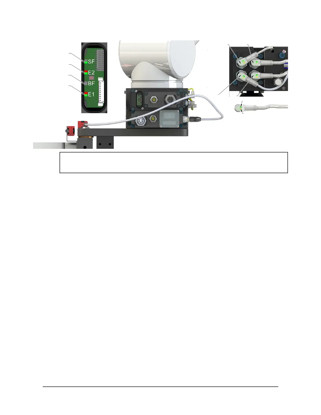
Figure 4.5—Master Coupled with Tool
RTL (R1)
Unlock (U)
RTL (R2)
Lock (L)
Green LED (Power)
Yellow LED
(Switch Made)
SF LED is Green
E2 LED is Red/Green
BF LED is Off
E1 LED is Red/Green
NOTICE: If the LEDs don’t match what is shown, refer to Section 2.1.2—System Failure (SF)
and Bus Failure (BF) LEDs or Section 2.1.3—Ethernet 1 and Ethernet 2 LEDs for possible
issues.
5. Couple the Tool Changer.
a. If ON, turn the Unlatch output OFF and turn the Latch output ON. (Note: Even for units
with single solenoids the Latch output must be turned ON.)
b. With the Latch output ON, power is available on the Tool and the Tool Power is ON input
turns ON.
c. The Unlocked input turns OFF and a short time later the Locked input turns ON and
remains ON, indicating that the Tool Changer locking mechanism latch operation is
complete. After the Locked input turns ON, the Latch output can be turned OFF.
d. Sometime thereafter, communications should be established with the downstream
PROFINET device(s). (The time it takes to establish connection with a downstream
PROFINET node depends on the power up and reconnect time of the individual
PROFINET equipment that is installed on the Tool.)