Manual, Control Module, PROFINET, DL10
Document #9620-20-C-DL10-04
Pinnacle Park • 1031 Goodworth Drive • Apex, NC 27539 • Tel: 919.772.0115 • Fax: 919.772.8259 • www.ati-ia.com
C-36
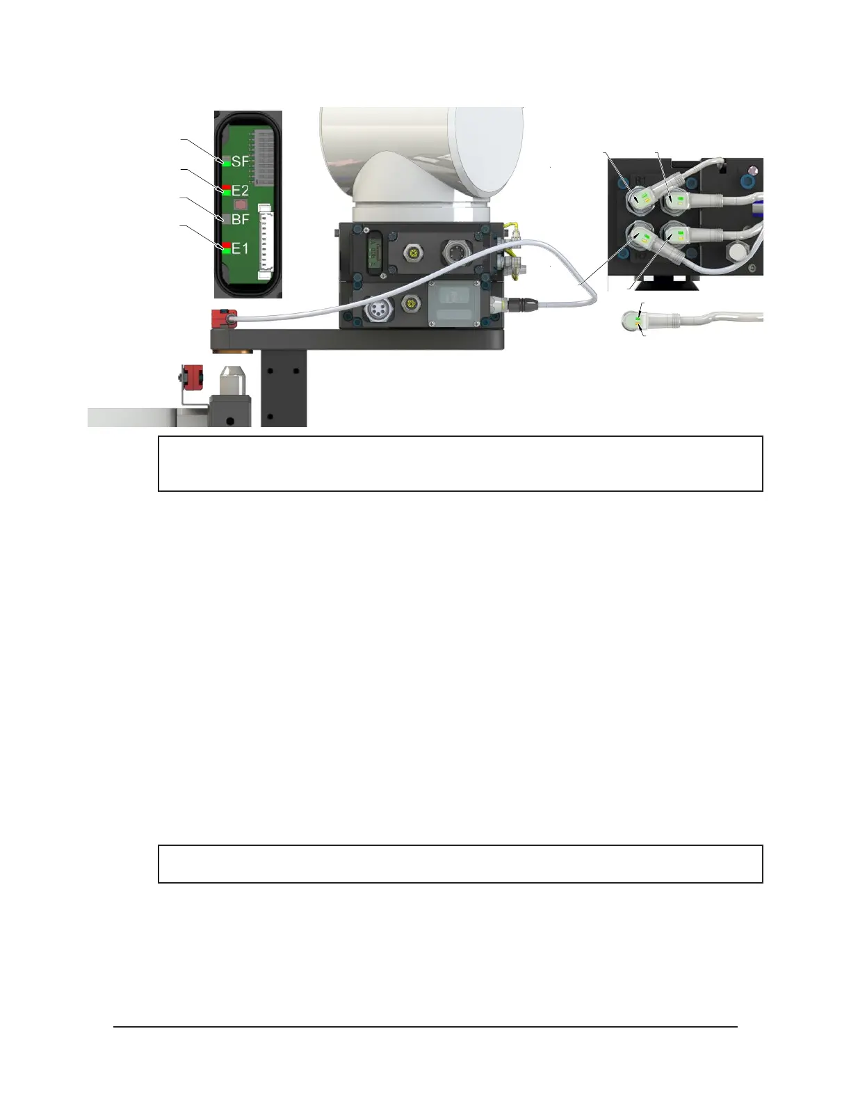
Figure 4.6—Master Coupled with Tool Moves Out of the Stand
RTL (R1)
Unlock (U)
RTL (R2)
Lock (L)
Green LED (Power)
Yellow LED
(Switch Made)
SF LED is Green
E2 LED is Red/Green
BF LED is Off
E1 LED is Red/Green
NOTICE: If the LEDs don’t match what is shown, refer to Section 2.1.2—System Failure (SF)
and Bus Failure (BF) LEDs or Section 2.1.3—Ethernet 1 and Ethernet 2 LEDs for possible
issues.
6. The robot moves away from the tool stand with the Tool Changer coupled.
a. The TSI Limit Switch is deactivated, and the TSIV and TSRV input goes OFF.
b. The Unlatch Enabled turns OFF.
7. Normal operation.
a. The following inputs are ON:
ii. Locked
iii. Input/Logic Power Good
iv. Output Power Available
v. RTL1 and RTL2
vi. Tool Present
vii. Tool Power is On
viii. RTLV1 and RTLV2
ix. Tool-ID
b. The following inputs are OFF:
i. Unlocked
ii. TSRV
iii. TSIV
iv. Unlatch Enabled
NOTICE: The Latch output can be turned OFF, after the Locked input indicates the Tool
Changer is in the locked state.
c. The following output is OFF:
i. Unlatch
ii. Latch