Manual, Control Module, PROFINET, DL10
Document #9620-20-C-DL10-04
Pinnacle Park • 1031 Goodworth Drive • Apex, NC 27539 • Tel: 919.772.0115 • Fax: 919.772.8259 • www.ati-ia.com
C-37
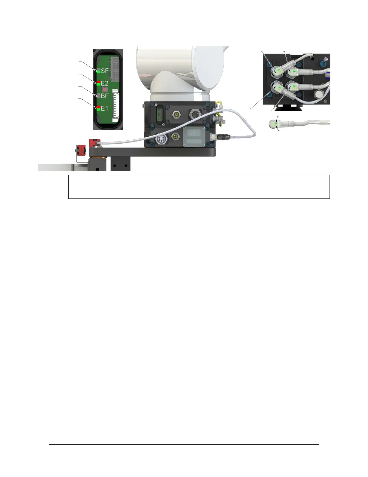
Figure 4.7—Master Coupled with Tool Returned to Stand
RTL (R1)
Unlock (U)
RTL (R2)
Lock (L)
Green LED (Power)
Yellow LED
(Switch Made)
SF LED is Green
E2 LED is Red/Green
BF LED is Off
E1 LED is Red/Green
NOTICE: If the LEDs don’t match what is shown, refer to Section 2.1.2—System Failure (SF)
and Bus Failure (BF) LEDs or Section 2.1.3—Ethernet 1 and Ethernet 2 LEDs for possible
issues.
8. The robot moves into the tool stand with the Tool Changer coupled.
a. When the tool is returned to the stand, the TSI Limit Switch is activated and the TSIV and
TSRV inputs goes ON.
b. The Unlatch Enabled is ON, indicating that it is safe to uncouple the Tool Changer.
9. Uncouple the Tool Changer.
a. If ON, turn the Latch output OFF and turn the Unlatch output ON.
b. The Tool Power is ON input is OFF and the power on the Tool turns off.
c. Communication is lost with downstream device(s).
d. The Locked input turns OFF and a short time later the Unlocked input turns ON and
remains ON, indicating that the Tool Changer locking mechanism unlatch operation is
complete. For units with double solenoid valves, after the Unlocked input turns ON, the
Unlatch output can be turned OFF.