Manual, Control Module, PROFINET, DL10
Document #9620-20-C-DL10-04
Pinnacle Park • 1031 Goodworth Drive • Apex, NC 27539 • Tel: 919.772.0115 • Fax: 919.772.8259 • www.ati-ia.com
C-44
6. Connect the RTL1, RTL2, Lock, and Unlock sensor cables to the connectors on the
Master module.
7. Connect the power cable to the connector on the Master module.
8. Connect the ground to the grounding terminal.
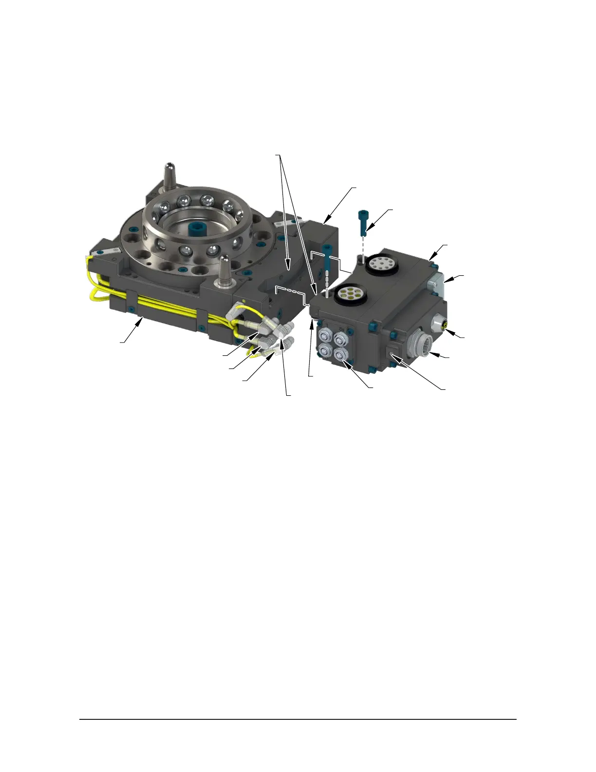
Figure 6.2—Master Module Installation
Valve Adapter (JT2-M Shown)
RTL, Lock,
and Unlock
Sensor Connectors
FE Ground Connection
with M8 set screw
(2) M6 Socket Head Cap Screw
L Connector
U Connector
R2 Connector
R1 Connector
Valve Signal
Pin Block
LEDs and
the Reset Switch
Use the Ledge Mounting Feature
to Properly Align the Module
Power
Connector
PROFINET
Connector
Master Module
9. Loosen (2) M3 captive head screws using a Phillips head screwdriver and remove
LED window.
10. Locate Reset button between BF and E2 LED.
11. Use a non‑conductive tool (e.g. plastic stylus) to press on the Reset Button ‑> the
SF LED will change from GREEN to blinking RED, indicating that the DL10‑M
module will clear its name and IP address after the next power‑cycle.
12. Re‑install the window and tighten the (2) M3 pan head captive screws using a
Phillips head screwdriver.