Manual, Control Module, PROFINET, DL10
Document #9620-20-C-DL10-04
Pinnacle Park • 1031 Goodworth Drive • Apex, NC 27539 • Tel: 919.772.0115 • Fax: 919.772.8259 • www.ati-ia.com
C-45
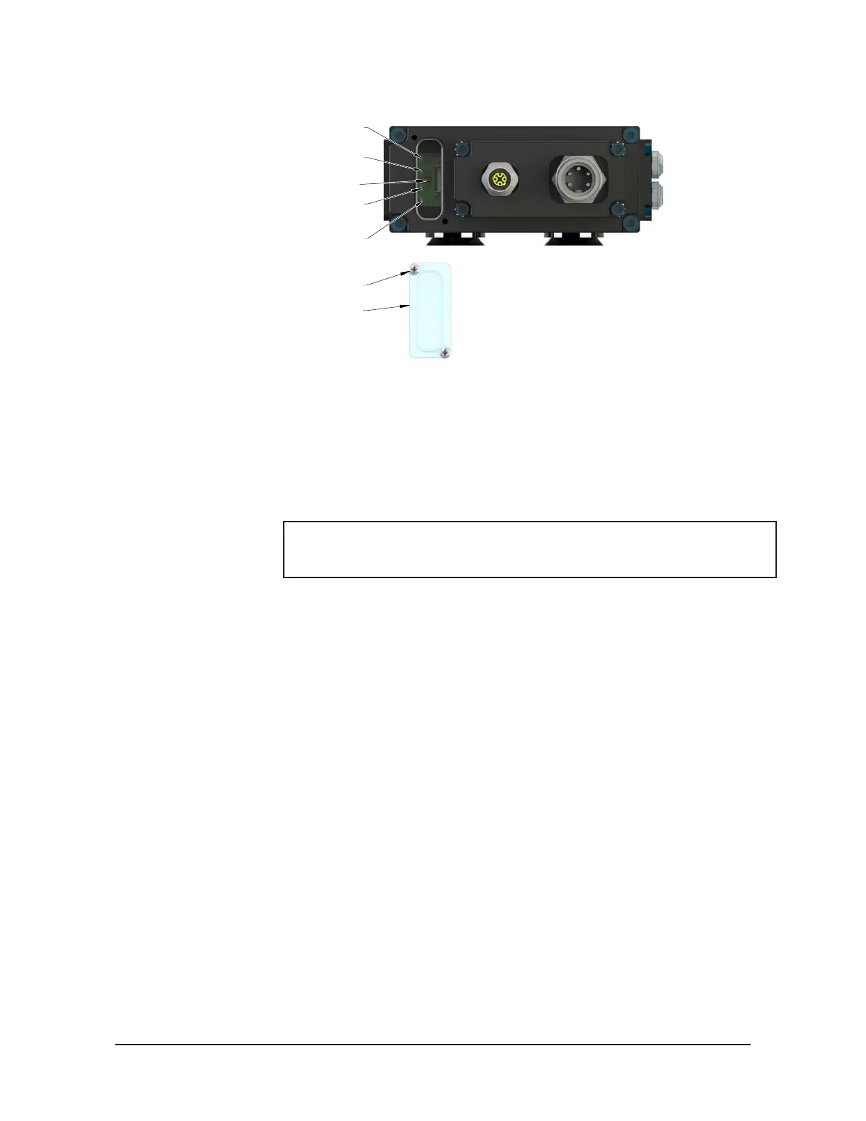
Figure 6.3—Reset Button
System Failure (SF) LED
Ethernet (E2) LED
Robot-Side Ethernet Port
Ethernet (E1) LED
Tool-Side Ethernet Port
Bus Failure (BF) LED
Reset Button
(Reset to Factory Settings)
(2) M3 Captive Head Screw
Window
13. The new module may be found using the default PROFINET station name and
congured to the appropriate station name for your application, or the network
controller may be congured to automatically rename the module when it detects
the default name.
14. Disconnect the 5‑pin power cable to the Master module.
15. Connect the M12 Ethernet cable and the 5‑pin power cable to the connectors on the
Master module.
NOTICE: Within a few seconds after conguring, the Master module is
operating on the network. The SF and BF LEDs are GREEN, when the
network is operating without errors. Refer to Section 2.4—Tool Side TSI.
16. After repair is complete, return all circuits to normal operation (e.g. electrical, air,
water, etc.).