- 37 -
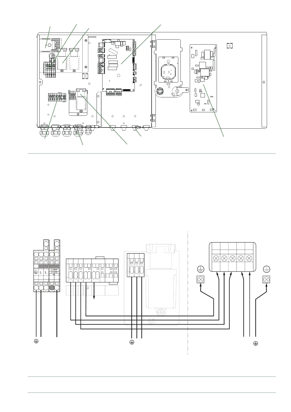
fi g. 35 - Description of the hydraulic module's electrical control box
HP controller
Cable grommets (power)
Interface Board
Cable grommets (sensors)
DHW Relay + Terminal
Terminal
Power supply terminal block
Power Relay for electric backup
Safety thermostat
fi g. 36 - Connection to terminal blocks and power relay
L
N
123
45 67
1
2
3
4
5
L
N
COM
L
123 LN
L
N
L
N
Outdoor unitHydraulic unit
Power supply
230 V
Power supply
Domestic Hot Water
230 V
towards external
component
contact*
red
blue
brown
green/yellow
Interconnection
between outdoor unit
and hydraulic unit
Power supply
Electrical backup
230 V
* If the control device does not provide a potential-free contact, the contact must be relayed to create an equivalent wiring.
In any case, refer to the instructions for the external components (power limiting device, electricity meter, etc.) to create the wiring.
Alfea Extensa A.I. R32 / INSTALLATION / 2114 - EN