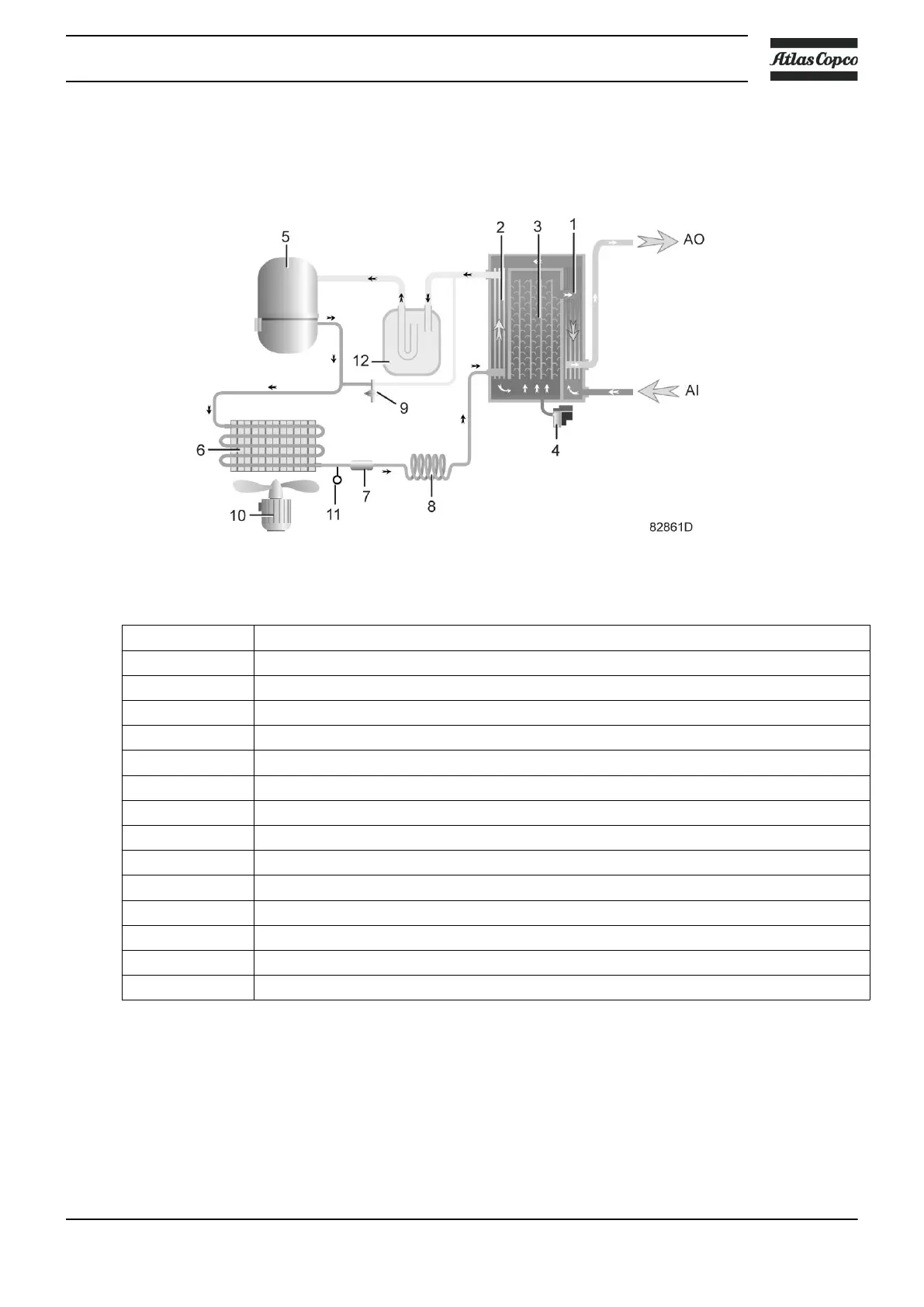
2.6 Air dryer
Flow diagram
Air dryer
Reference Name
AI Air inlet
AO Air outlet
1 Air/air heat exchanger
2 Air/refrigerant heat exchanger/evaporator
3 Condensate separator
4 Automatic drain / condensate outlet
5 Refrigerant compressor
6 Refrigerant condenser
7 Liquid refrigerant dryer/filter
8 Capillary
9 Bypass valve
10 Condenser cooling fan
11 Pressure switch, fan control
12 Liquid separator
Compressed air circuit
Compressed air enters the heat exchanger (1) and is cooled by the outgoing, cold, dried air.
Water in air starts to condense. Then, the air flows through the heat exchanger/evaporator (2),
where the refrigerant evaporates.
This causes the air to cool further close to the evaporating temperature of the refrigerant. More
water in the air condenses.
Instruction book
2920 7110 05 25
 Loading...


