72
Instruction book
9096 3313 00
4.2 Operation
General
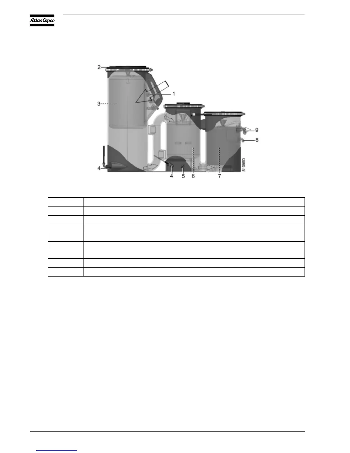
The OSCi 3790 housing consists of 3 interconnected vessels. The oil-containing condensate is injected (1)
indiscontinuous bursts at a downward angle into the first vessel which acts as expansion chamber. The
speciallydesigned cover has a combination of pressure-relieving holes and a foam (2). Since the pressure is
relievedhere, the entire OSCi device is pressureless. In the first vessel, a floating filter (3) made of special
syntheticfibres takes up most of the directly separable hydrocarbons from the condensate. The filter sinks
as it saturateswith hydrocarbons and hence the lifetime progress of the filter can be measured by an
indicator that rests onthe bag. A conventional sight glass is installed for visual inspection of the filter position
and the condensatelevel. On top of that, an electronic position sensor (8 - View of OSCi, 1 - View of OSCi
inlet) is connectedto the Elektronikon® regulator of the compressor to keep track of the filter lifetime
without the need to openthe compressor canopy.
The outlet of the first vessel is situated at the bottom and is connected to the upper half of the second
vessel.In the second vessel, the pre-filtered condensate is brought in contact with a filter bag (6), filled with
OleophilicGranular Clay (OGC). Through a connection (5) at the bottom of the second vessel, air is injected
into the condensate. This airflow breaks stable emulsions by enhancing the sorption process of oil onto the
OGC. Theair supply also prevents the formation of certain anaerobic bacteria. Also the cover of the second
vessel isequipped with ventilation holes to prevent pressure buildup. The airflow is taken from the
aftercooler (on aircooled units) or from the water separator (WSD) (on water cooled units). An integrated
nozzle with strainerlimits the airflow (approximately 450 l/h at reference conditions), while a solenoid valve
makes sure nocompressed air is used when the compressor is not delivering air.
1 Condensate inlet
2 Foam cover
3 Oleophilic filter
4 Service drains with valve
5 Air injection connection
6 OGC filter
7 Activated carbon filter
8 Condensate test outlet
9 Condensate outlet
Condensate flow scheme
 Loading...


