ATtiny15L
12
The most typical and general program setup for the Reset and Interrupt Vector Addresses are:
Address Labels Code Comments
$000 rjmp RESET ; Reset handler
$001 rjmp EXT_INT0 ; IRQ0 handler
$002 rjmp PIN_CHANGE ; Pin change handler
$003 rjmp TIM1_CMP ; Timer1 compare match
$004 rjmp TIM1_OVF ; Timer1 overflow handler
$005 rjmp TIM0_OVF ; Timer0 overflow handler
$006 rjmp EE_RDY ; EEPROM Ready handler
$007 rjmp ANA_COMP ; Analog Comparator handler
$008 rjmp ADC ; ADC Conversion Handler
;
$009 MAIN: <instr> xxx ; Main program start
…… ……
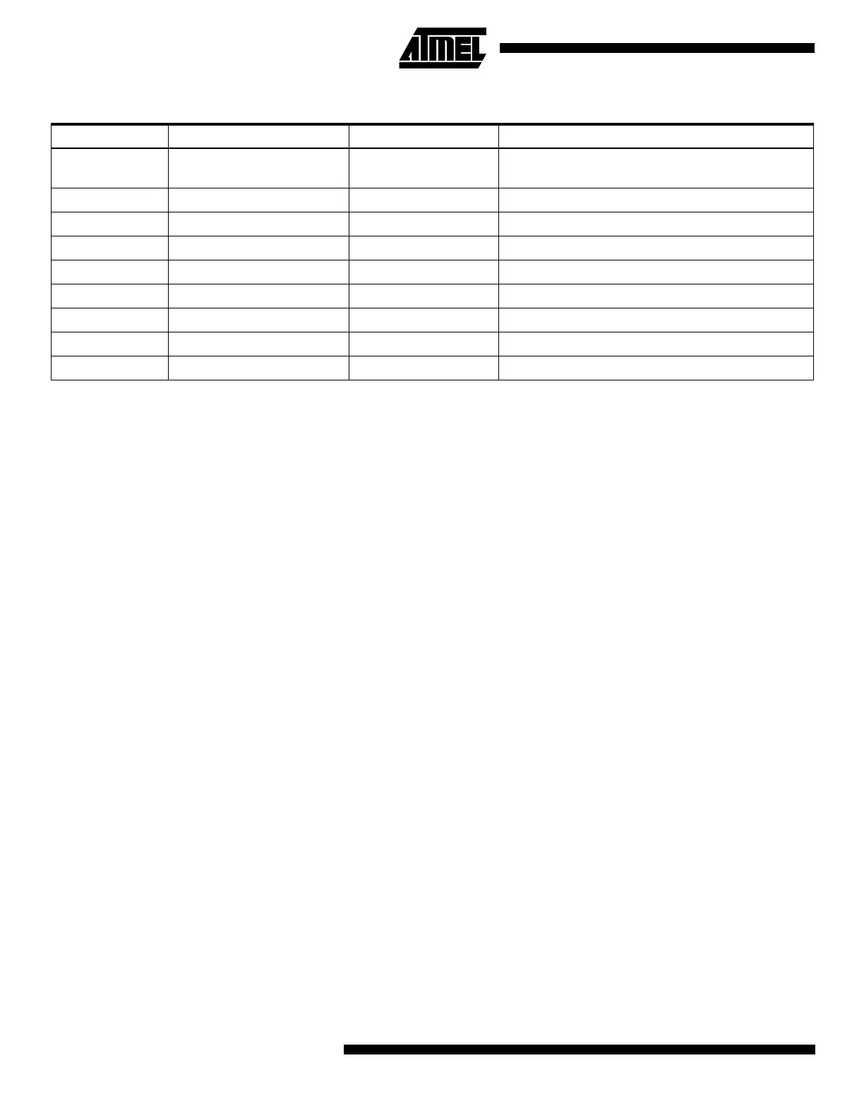
Table 3. Reset and Interrupt Vectors
Vector No. Program Address Source Interrupt Definition
1 $000 RESET
External Reset, Power-on Reset, Brown-out Reset,
and Watchdog Reset
2 $001 INT0 External Interrupt Request 0
3 $002 I/O Pins Pin Change Interrupt
4 $003 TIMER1, COMPA Timer/Counter1 Compare Match A
5 $004 TIMER1, OVF Timer/Counter1 Overflow
6 $005 TIMER0, OVF Timer/Counter0 Overflow
7 $006 EE_RDY EEPROM Ready
8 $007 ANA_COMP Analog Comparator
9 $008 ADC ADC Conversion Complete
 Loading...


