ATtiny15L
41
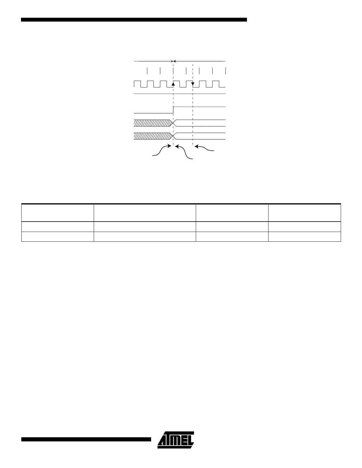
Figure 29. ADC Timing Diagram, Free Running Conversion
ADC Noise Canceler Function
The ADC features a noise canceler that enables conversion during ADC Noise Reduction mode (see “Sleep Modes” on
page 22) to reduce noise induced from the CPU core and other I/O peripherals. If other I/O peripherals must be active dur-
ing conversion, this mode works equivalently for Idle mode. To make use of this feature, the following procedure should be
used:
1. Make sure that the ADC is enabled and is not busy converting. Single Conversion mode must be selected and the
ADC conversion complete interrupt must be enabled.
ADEN = 1
ADSC = 0
ADFR = 0
ADIE = 1
2. Enter ADC Noise Reduction mode (or Idle mode). The ADC will start a conversion once the CPU has been halted.
3. If no other interrupts occur before the ADC conversion completes, the ADC interrupt will wake-up the MCU and exe-
cute the ADC conversion complete interrupt routine.
Table 17. ADC Conversion Time
Condition
Sample & Hold
(cycles from start of conversion) Conversion Time (cycles) Conversion Time (µs)
Extended Conversion 13.5 25 125 - 500
Normal Conversions 1.5 13 65 - 260
11 12 13
Sign and MSB of result
LSB of result
ADC clock
ADSC
ADIF
ADCH
ADCL
Cycle number
12
One Conversion Next Conversion
34
Conversion
complete
Sample & hold
MUX and REFS
update

 Loading...


