ATtiny15L
40
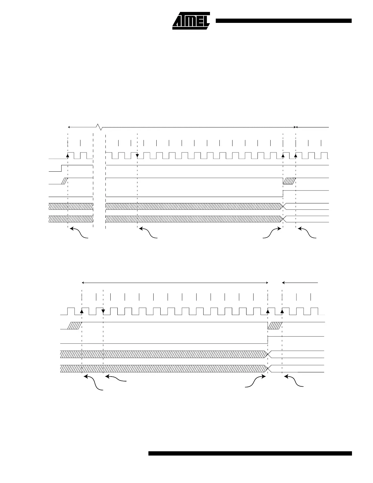
The actual sample-and-hold takes place 1.5 ADC clock cycles after the start of a normal conversion and 13.5 ADC clock
cycles after the start of an extended conversion. When a conversion is complete, the result is written to the ADC data reg-
isters, and ADIF is set. In single conversion mode, ADSC is cleared simultaneously. The software may then set ADSC
again, and a new conversion will be initiated on the first rising ADC clock edge. In Free Running mode, a new conversion
will be started immediately after the conversion completes, while ADSC remains high. Using Free Running mode and an
ADC clock frequency of 200 kHz gives the lowest conversion time, 65
µs, equivalent to 15 kSPS. For a summary of conver-
sion times, see Table 17.
Figure 27. ADC Timing Diagram, First Conversion (Single Conversion Mode)
Figure 28. ADC Timing Diagram, Single Conversion
Sign and MSB of result
LSB of result
ADC clock
ADSC
Sample & hold
ADIF
ADCH
ADCL
Cycle number
ADEN
1 212
13
14 15
16 17
18
19 20 21 22 23
24 25
1 2
Extended Conversion
Next
Conversion
3
MUX and REFS
update
MUX and REFS
update
Conversion
complete
1
2 3 4 5 6 7 8
9
10 11 12 13
Sign and MSB of result
LSB of result
ADC clock
ADSC
ADIF
ADCH
ADCL
Cycle number
12
One Conversion Next Conversion
3
Sample & hold
MUX and REFS
update
Conversion
complete
MUX and REFS
update
 Loading...


