ATtiny15L
25
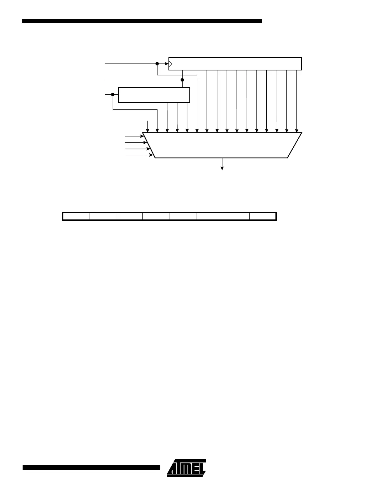
Figure 19. Timer/Counter1 Prescaler
The Special Function IO Register – SFIOR
• Bit 7...3 - Res: Reserved Bits
These bits are reserved bits in the ATtiny15L and always read as zero.
•
Bit 2 - FOC1A: Force Output Compare 1A
Writing a logical one to this bit forces a change in the compare match output pin PB1 (OC1A) according to the values
already set in COM1A1 and COM1A0. The Force Output Compare bit can be used to change the output pin without waiting
for a compare match in timer. The automatic action programmed in COM1A1 and COM1A0 happens as if a Compare
Match had occurred, but no interrupt is generated and the Timer/Counter1 will not be cleared even if CTC1 is set. The
FOC1A bit will always be read as zero. The setting of the FOC1A bit has no effect in PWM mode.
•
Bit 1 - PSR1: Prescaler Reset Timer/Counter1
When this bit is set (one) the Timer/Counter1 prescaler will be reset. The bit will be cleared by hardware after the operation
is performed. Writing a zero to this bit will have no effect. This bit will always be read as zero.
•
Bit 0 - PSR0: Prescaler Reset Timer/Counter0
When this bit is set (one) the Timer/Counter0 prescaler will be reset. The bit will be cleared by hardware after the operation
is performed. Writing a zero to this bit will have no effect. This bit will always be read as zero.
The 8-bit Timer/Counter0
Figure 20 shows the block diagram for Timer/Counter0.
The 8-bit Timer/Counter0 can select clock source from CK, prescaled CK, or an external pin. In addition, it can be stopped
as described in the specification for the Timer/Counter0 Control Register – TCCR0. The overflow status flag is found in the
Timer/Counter Interrupt Flag Register – TIFR. Control signals are found in the Timer/Counter0 Control Register – TCCR0.
The interrupt enable/disable settings for Timer/Counter0 are found in the Timer/Counter Interrupt Mask Register – TIMSK.
When Timer/Counter0 is externally clocked, the external signal is synchronized with the oscillator frequency of the CPU. To
ensure proper sampling of the external clock, the minimum time between two external clock transitions must be at least one
internal CPU clock period. The external clock signal is sampled on the rising edge of the internal CPU clock.
Bit 76543210
$2C - - - - - FOC1A PSR1 PSR0 SFIOR
Read/Write R R R R R R/W R/W R/W
Initial value 0 0 0 0 0 0 0 0
10-BIT T/C PRESCALER
TIMER/COUNTER1 CLOCK SOURCE
CK
PSR1
CS10
CS11
CS12
CK/8
CK/256
CK/1024
CK/64
PCK
(25.6 MHz)
(1.6 MHz)
0
CS13
CLEAR
CLEAR
3-BIT T/C PRESCALER
PCK/2
PCK/4
PCK/8
CK (=PCK/16)
CK/2
CK/4
CK/16
CK/32
CK/128
CK/512

 Loading...


