ATtiny15L
13
ATtiny15L Reset Sources
The ATtiny15L has four sources of reset:
• Power-on Reset. The MCU is reset when the supply voltage is below the power-on reset threshold (V
POR
).
• External Reset. The MCU is reset when a low-level is present on the RESET pin for more than 500 ns.
• Watchdog Reset. The MCU is reset when the Watchdog timer period expires, and the Watchdog is enabled.
• Brown-out Reset. The MCU is reset when the supply voltage V
CC
is below the Brown-out reset threshold (V
BOT
).
During reset, all I/O registers are then set to their initial values, and the program starts execution from address $000. The
instruction placed in address $000 must be an RJMP – relative jump – instruction to the reset handling routine. If the pro-
gram never enables an interrupt source, the interrupt vectors are not used, and regular program code can be placed at
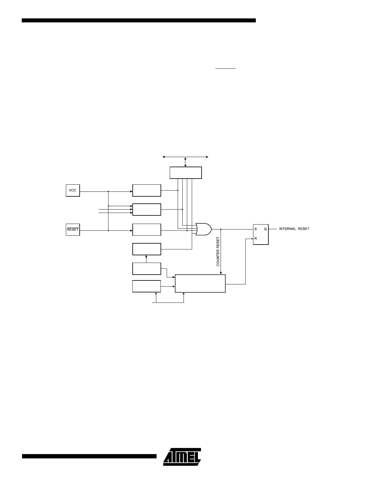
these locations. The circuit diagram in Figure 12 shows the reset logic. Table 4 and Table 5 define the timing and electrical
parameters of the reset circuitry. Note that the register file is unchanged by a reset.
Figure 12. Reset Logic
MCU Status
Register (MCUSR)
Brown-Out
Reset Circuit
BODEN
BODLEVEL
Delay Counters
CKSEL[1:0]
CK
TIMEOUT
WDRF
BORF
EXTRF
PORF
DATA BUS
Tunable Internal
Oscillator
Watchdog
Oscillator
Watchdog
Timer
Reset Circuit
Power-ON Reset
Circuit
 Loading...


