ATtiny15L
31
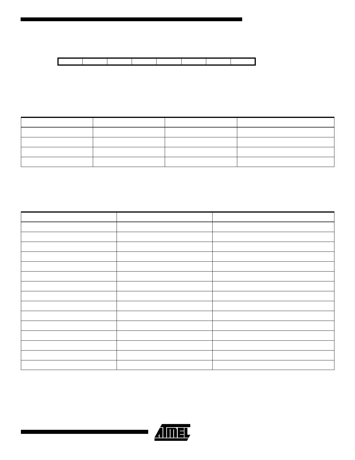
Timer/Counter1 Output Compare RegisterB – OCR1B
The output compare register1 OCR1B is an 8-bit read/write register. This register is used in the PWM mode only, and it lim-
its the top value to which the Timer/Counter1 keeps counting. After reaching OCR1B in PWM mode, the counter starts from
$00.
In PWM mode, the Timer Overflow Flag – TOV1 – is set as in normal timer/counter mode. Timer Overflow Interrupt1 oper-
ates exactly as in normal Timer/Counter mode, i.e. it is executed when TOV1 is set provided that Timer Overflow Interrupt
and global interrupts are enabled. This also applies to the Timer Output Compare A flag and interrupt.
The frequency of the PWM will be Timer Clock Frequency divided by OCR1B value + 1.
Bit 76543210
$2D MSB LSB OCR1B
Read/Write R/W R/W R/W R/W R/W R/W R/W R/W
Initial value 1 1 1 1 1 1 1 1
Table 13. PWM Outputs when OCR1A = $00 or OCR1B
COM1A1 COM1A0 OCR1B Output PWMn
10$00 L
10OCR1B H
11$00 H
11OCR1B L
Table 14. Timer/Counter1 Clock Prescale Select
Clock Selection OCR1B PWM Frequency
CK 159 10 kHz
PCK/8 159 20 kHz
PCK/4 213 30 kHz
PCK/4 159 40 kHz
PCK/2 255 50 kHz
PCK/2 213 60 kHz
PCK/2 181 70 kHz
PCK/2 159 80 kHz
PCK/2 141 90 kHz
PCK 255 100 kHz
PCK 231 110 kHz
PCK 213 120 kHz
PCK 195 130 kHz
PCK 181 140 kHz
PCK 169 150 kHz
 Loading...


