EasyManua.ls Logo

Atmel AVR ATtiny15L User Manual

Atmel AVR ATtiny15L
85 pages
To Next Page IconTo Next Page
To Previous Page IconTo Previous Page
Page #47 background imageLoading...
Page #47 background image
47
ATtiny15L
1187H–AVR–09/07
Bits 4..3 – Res: Reserved Bits
These bits are reserved bits in the ATtiny15L and always read as zero.
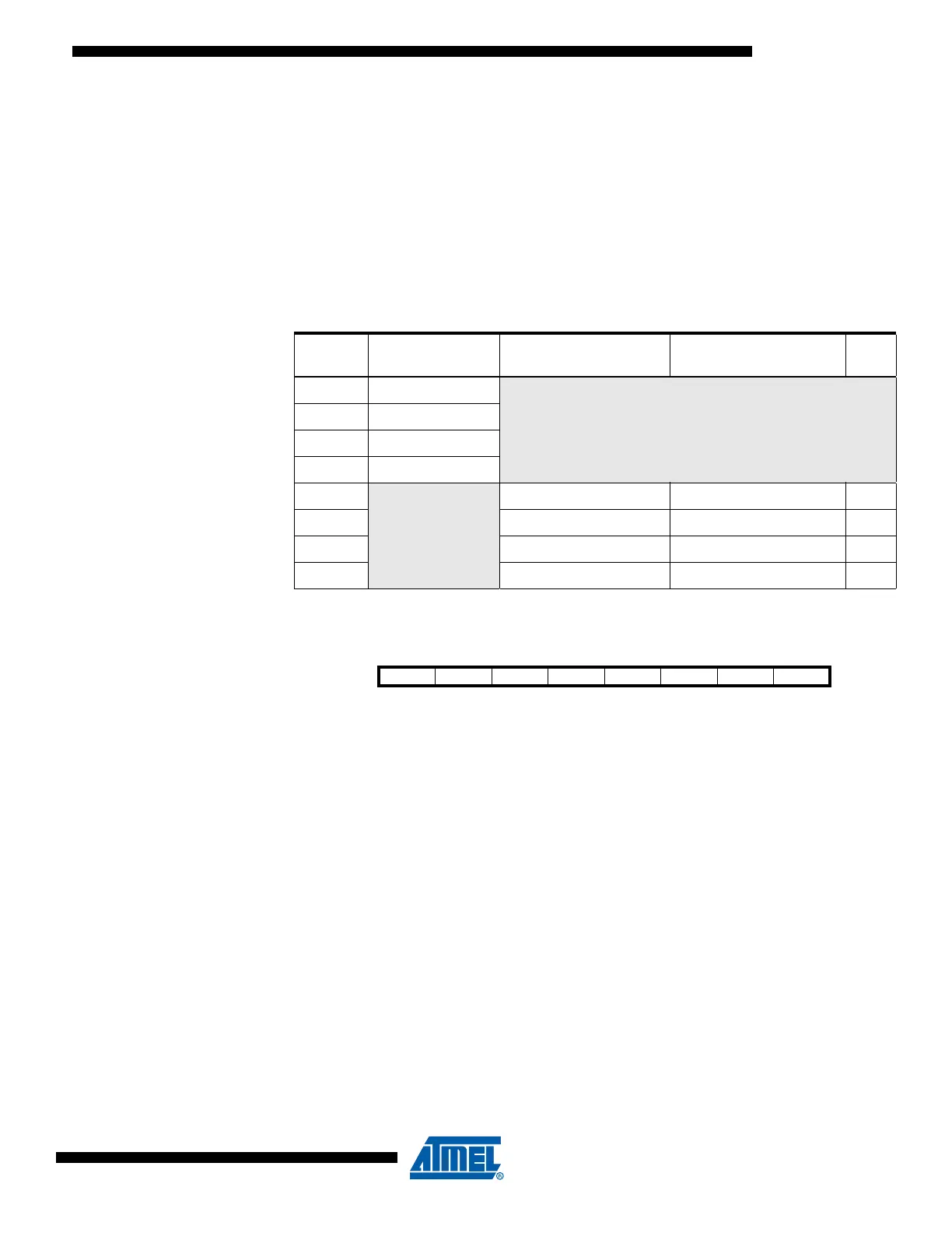
Bits 2..0 – MUX2..MUX0: Analog Channel and Gain Selection Bits 2..0
The value of these bits selects which analog input is connected to the ADC. In case of
differential input (PB3 - PB4), gain selection is also made with these bits. Selecting PB3
as both inputs to the differential gain stage enables offset measurements. Refer to Table
20 for details. If these bits are changed during a conversion, the change will not go into
effect until this conversion is complete (ADIF in ADCSR is set).
Note: 1. For offset calibration only. See “Operation” on page 42.
The ADC Control and Status
Register – ADCSR
Bit 7 – ADEN: ADC Enable
Writing a logical “1” to this bit enables the ADC. By clearing this bit to zero, the ADC is
turned off. Turning the ADC off while a conversion is in progress will terminate this
conversion.
Bit 6 – ADSC: ADC Start Conversion
In Single Conversion mode, a logical “1” must be written to this bit to start each conver-
sion. In Free Running mode, a logical “1” must be written to this bit to start the first
conversion.
When the conversion completes, ADSC returns to zero in Single Conversion mode and
stays high in Free Running mode.
Writing a “0” to this bit has no effect.
Bit 5 – ADFR: ADC Free Running Select
When this bit is set (one), the ADC operates in Free Running mode. In this mode, the
ADC samples and updates the Data Registers continuously. Clearing this bit (zero) will
terminate Free Running mode. If active channels are used (MUX2 in ADMUX set), the
Table 20. Input Channel and Gain Selections
MUX2..0
Single-ended
Input
Positive
Differential Input
Negative
Differential Input Gain
000 ADC0 (PB5)
N/A
001 ADC1 (PB2)
010 ADC2 (PB3)
011 ADC3 (PB4)
100
(1)
N/A
ADC2 (PB3) ADC2 (PB3) 1x
101
(1)
ADC2 (PB3) ADC2 (PB3) 20x
110 ADC2 (PB3) ADC3 (PB4) 1x
111 ADC2 (PB3) ADC3 (PB4) 20x
Bit 76543210
$06 ADEN ADSC ADFR ADIF ADIE ADPS2 ADPS1 ADPS0 ADCSR
Read/Write R/W R/W R/W R/W R/W R/W R/W R/W
Initial Value00000000

Table of Contents

Other manuals for Atmel AVR ATtiny15L

Question and Answer IconNeed help?

Do you have a question about the Atmel AVR ATtiny15L and is the answer not in the manual?

Atmel AVR ATtiny15L Specifications

General IconGeneral
Architecture8-bit AVR
Flash Memory1 KB
SRAM64 Bytes
I/O Pins6
ADC Channels4
Temperature Range-40°C to +85°C
Operating Voltage2.7V - 6.0V
Timers1 x 8-bit
Package8-pin PDIP, SOIC

Summary

Features

Non-volatile Program and Data Memories

1K Byte Flash Program Memory and 64 Bytes EEPROM.

Description

Block Diagram

Pin Descriptions

ATtiny15L Architectural Overview

The General Purpose Register File

Details the 32 general purpose working registers and their access.

The ALU - Arithmetic Logic Unit

Explains the Arithmetic Logic Unit's operation and integration.

The Flash Program Memory

Describes the 1K byte Flash memory, its organization and endurance.

Reset and Interrupt Handling

Interrupt Handling

External Interrupt

Pin Change Interrupt

The MCU Control Register – MCUCR

Sleep Modes

Defines Idle, ADC Noise Reduction, and Power-down modes.

Tuneable Internal RC Oscillator

Timer/Counters

The Timer/Counter0 Prescaler

Details prescaler options for Timer/Counter0.

The Timer/Counter1 Prescaler

Details prescaler options for Timer/Counter1.

The 8-bit Timer/Counter0

Explains Timer/Counter0 operation, clock sources, and control.

The 8-bit Timer/Counter1

Describes Timer/Counter1, including PWM capabilities.

The Watchdog Timer

EEPROM Read/Write Access

Preventing EEPROM Corruption

Techniques to avoid data corruption during low voltage or reset.

The Analog Comparator

The Analog-to-Digital Converter, Analog Multiplexer, and Gain Stages

I/O Port B

Memory Programming

Electrical Characteristics

Absolute Maximum Ratings

Specifies limits beyond which damage may occur.

Typical Characteristics

ATtiny15L Register Summary

ATtiny15L Instruction Set Summary

Ordering Information

Packaging Information

Related product manuals