6
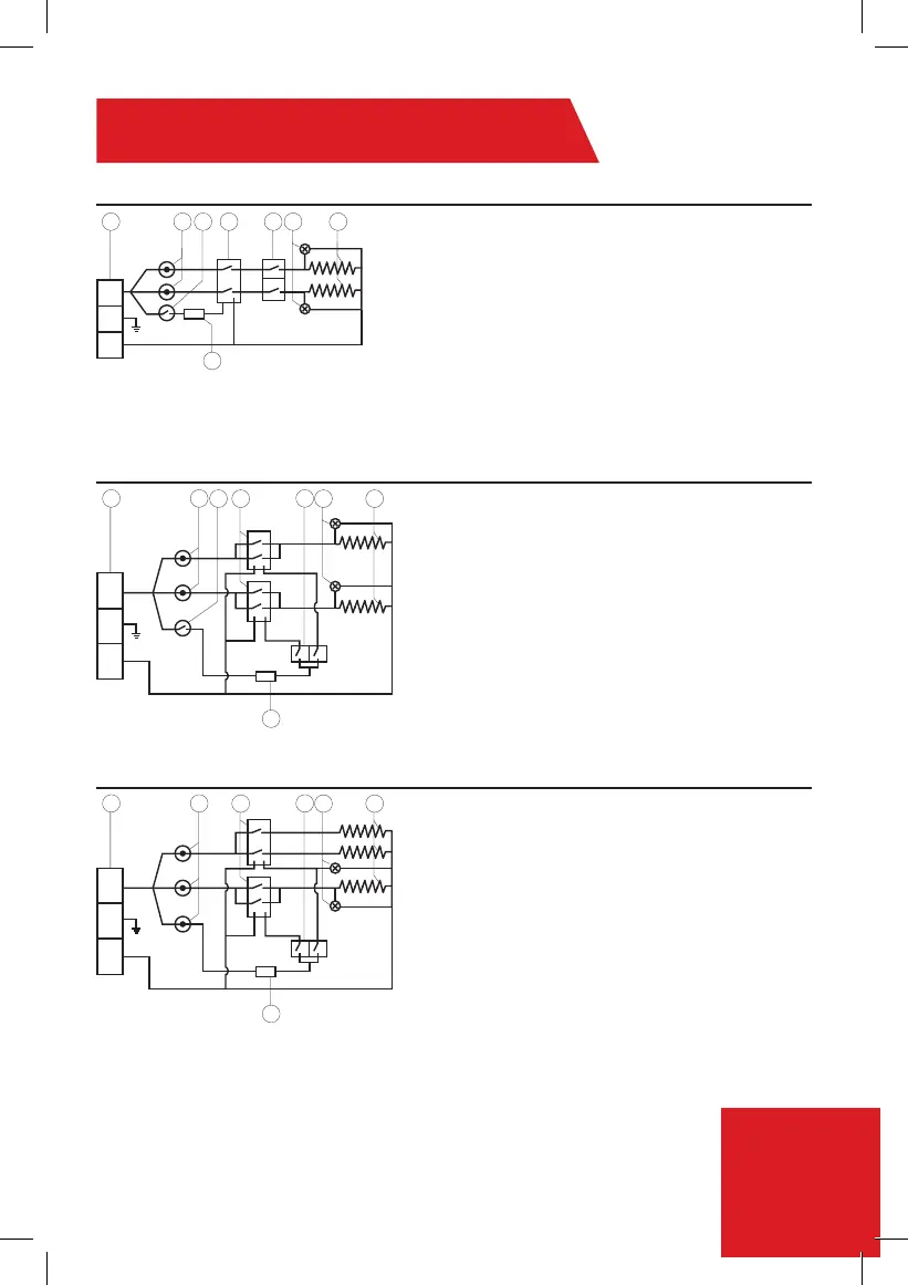
Diagrama eléctrico
1. Bloque de terminales
2. Interruptor térmico con reajuste
3. Interruptor térmico
4. Relé
5. Interruptor 0- Apagado
1- Bajo
2- Medio
3- Alto
6. Luz
7. Resistencia
8. Sensor de lectura
1. Bloque de terminales
2. Interruptor térmico con reajuste
3. Interruptor térmico
4. Relé
5. Interruptor 0- Apagado
1- Bajo
2- Medio
3- Alto
6. Luz
7. Resistencia
8. Sensor de lectura
1. Bloque de terminales
2. Interruptor térmico con reajuste
4. Relé
5. Interruptor 0- Apagado
1- Bajo
2- Medio
3- Alto
6. Luz
7. Resistencia
8. Sensor de lectura
8.5kW-10.5kW (240V)
13kW (240V)
3.0 (110V), 3.8 -6.5Kw (240V) - Instalar Línea 1 (L1), E(G)-Tierra, Línea 2 (L2)
L1/L2 = Línea 1/Línea 2 (Negro o Rojo)
E(G) = Tierra (Verde/Amarillo)
*N = Neutro (Blanco o Plata)
*El neutro actúa como Línea 2 (L2) para 220 V/240 V
1 2
8
3 4 5 6 7
R.R
85
º
Led 1
Led 2
85
º
57
º
L1
G
L2
2
3 4 6 7
1 5
8
R.R
85
º
Led 1
Relay
Switch
Relay
Led 2
85
º
57
º
L1
G
L2
2
4 6 7
1 5
8
R.R
85
º
Led 2
Relay
Switch
Relay
Led 1
85
º
85
º
L1
G
L2