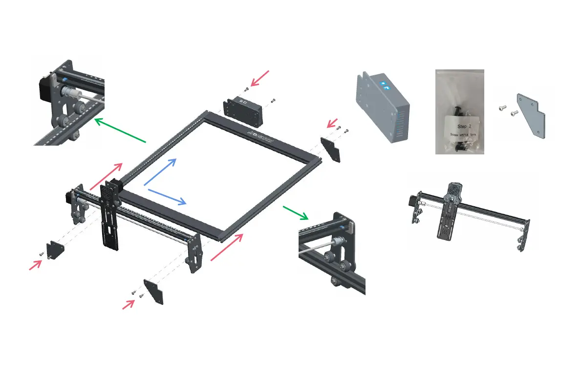
S t e p 2
Installation Manual:
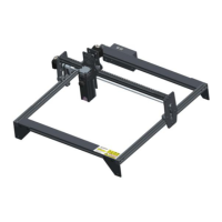
1.Push the X-axis component into the base frame
in the direction shown in the figure. Adjust the
eccentric nut appropriately.
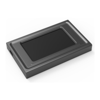
2.Install the control box as shown.
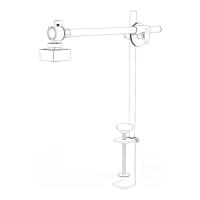
3. Use an M5 Allen key to install 3 Support gasket.
Control box *1
M5 screws*8
Support gasket *3
X-axis components*1
Step2 Required components:
1
1
2
3
3
3
The guide rail passes through
the middle of the 3 rollers.
Loosen the distance between the
upper and lower guide wheels
appropriately.
Y
X