Components required
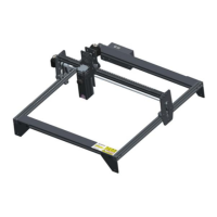
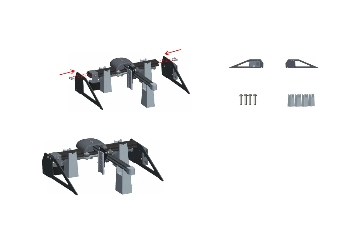
1. As shown in Figure 1, two assembly blocks are
used to install the Y-axis and one assembly block is
used to install the X-axis. They are respectively
clamped in different grooves, and then the upper
support foot and the lower support foot assembly
are assembled, and the support foot The
components and M5*14 screws are assembled to
the screw holes of the Y axis along the dotted lines
on both sides, and tighten the screws with a No. 4
Allen screwdriver
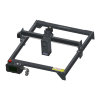
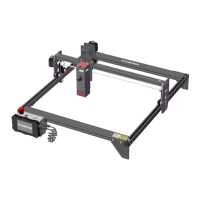
2. Figure 2 shows the complete assembly after the
Y-axis upper support foot and lower support foot
assembly and M5*14 screws are tightened.
Step 2
2
1
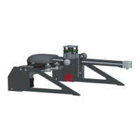
Upper support
foot and control
box component
Y-axis bracket screws
on both sides M5*14
Lower support
foot component
Assembly pad