SMA&SMQ - User manual 015
Chapter 4
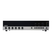
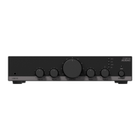
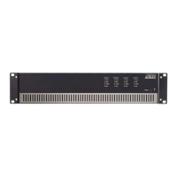
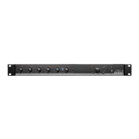
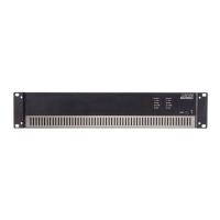
Connecting the amplier
Input connections
The signal input connections are performed using a balanced XLR and 3-pin terminal block (3.81 mm pitch)
connector for every input. Both connectors are linked in parallel, allowing free selection to which connector
the signal will be applied. If required, the second connector can be used for link-through of the applied signal
to other ampliers.
The input structure of the amplier is made exible due to the input selection matrix, meaning that any signal
applied to the amplier can be patched to any output channel. When driving multiple channels with the same
signal or summing stereo signals into a single mono signal (Eg. when the amplier is being used in bridged
mode), external links are redundant due to the input matrix.
Selecting and assigning the input signals to the amplier channels is made easy with the software congurable
user interface which is controllable using the front panel controls.
NOTE
Make sure the power is switched OFF when any change is made to the connections of the amplier.
 Loading...