SMA&SMQ - User manual 021
Mute
Output setup
Output setup >> Input list
Output setup >> Filters
Muting will completely suppress the signal of the selected output. The mute indicator is shown in green when the output
is unmuted and turns red when it is muted. Toggling between both states can be done by pressing the rotary function dial
once.
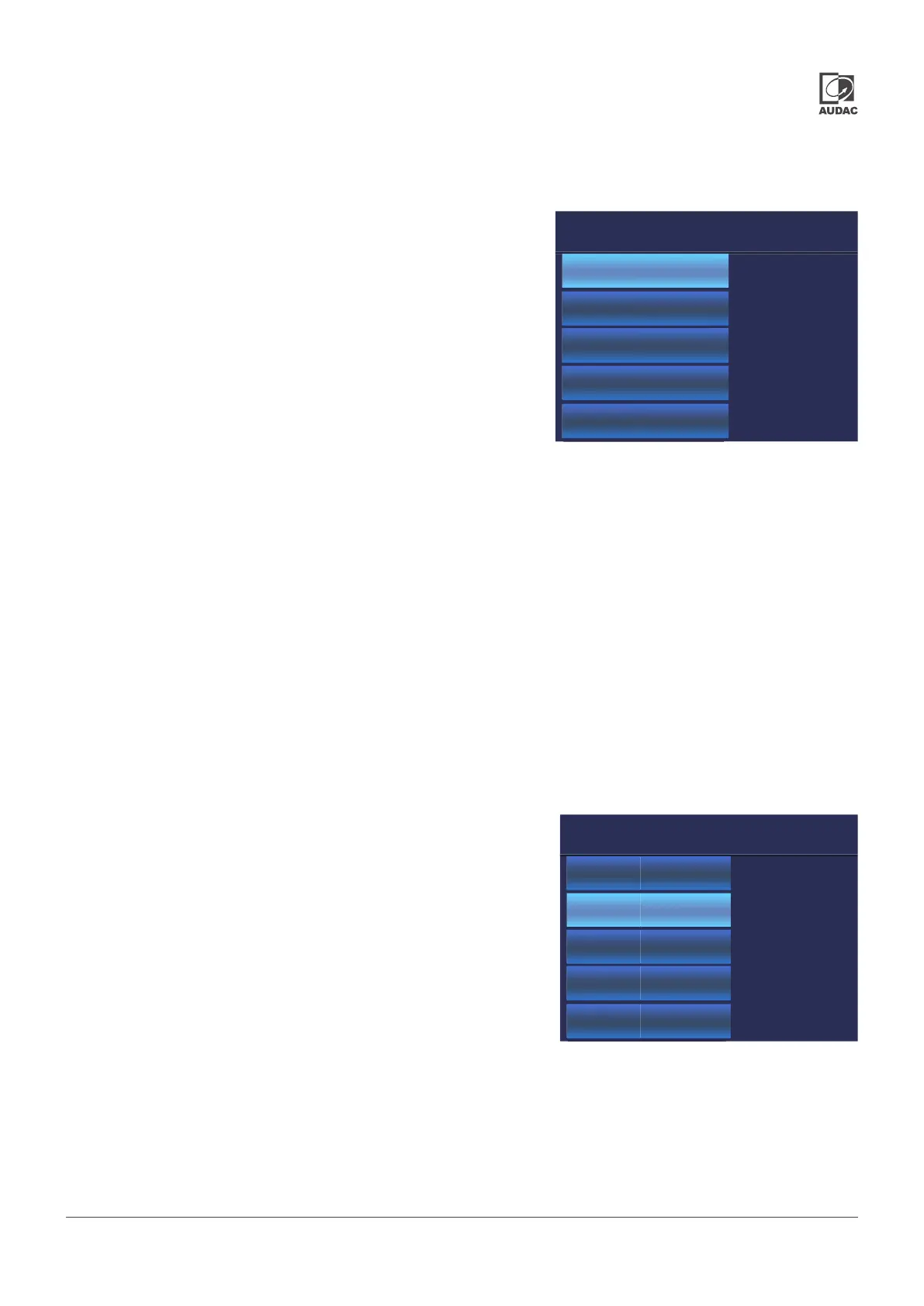
Output setup will lead you to a separate menu where the advanced
congurations for the corresponding output can be made. The output
setup menu is separately congurable for each of the outputs and includes
conguration settings which generally will be made once for every setup or
installation without having them adjusted frequently.
To return from the output setup menu back to the main menu, the ‘back’
option at the bottom needs to be pressed.
In the ‘Input list’, various inputs can be added, deleted and sorted. Only the inputs created here can be selected in the
‘Input’ list in the settings menu. This limits the options available.
In order to give different devices the same audio source, the given input has to be set according to the same numbering
scheme. For example: Device A has a sound source connected to INPUT1, device B has the same sound source
connected to INPUT4. In the Input list, the following is set:
Device A: 1 = INPUT 1
Device B: 1 = INPUT 4
Both devices are now playing the same audio when the same input list position is selected.
The SMA has two standard inputs where the SMQ has four standard inputs. When the optional ANI44XT module is
installed, four extra Dante™ inputs are added.
Filters are frequently used in audio systems for different purposes. Some
typical application examples are ltering noise or other unwanted signals from
an audio signal and separating audio signals between different frequency
ranges (crossover) when a 2-way (or more) system is used.
Because the characteristics of the required lter are strongly dependent of
the application, the lter settings are made exible and user congurable.
Two lters are available. These lters are a congurable ‘low pass’ and ‘high
pass’ lter. A ‘Band pass’ can be achieved combining a low and high pass
lter. Characteristics which can be congured for the lters are:
1 = INPUT 1
2 = INPUT 2
3 = INPUT 1+2
4 = INPUT 3
5 = INPUT 4
6 = INPUT 3+4
SETUP OUTPUT 1
Input List
Low pass
High pass
EQ settings
Delay
Type:
OFF
Roll-off: 24dB/Oct
Freq: 1000Hz
BACK
OUTPUT 1
Input List
Low pass
High pass
EQ settings
Delay
Filter Type: Selectable between Butterworth, Bessel, Linkwitz-Riley
Roll-off: Selectable between 12 dB/Oct and 24 dB/Oct
Cutoff frequency: Innitely adjustable between 1 Hz and 22 kHz
The conguration of the desired lter can be made by selecting the required lter type in the column on the left side (Low
pass or High pass). Subsequently the characteristics as described above can be adjusted on the right screen side. The
 Loading...