Copyright © 2006-2011 AudioNote Kits
www.AudioNoteKits.com
audionotekits@rogers.com
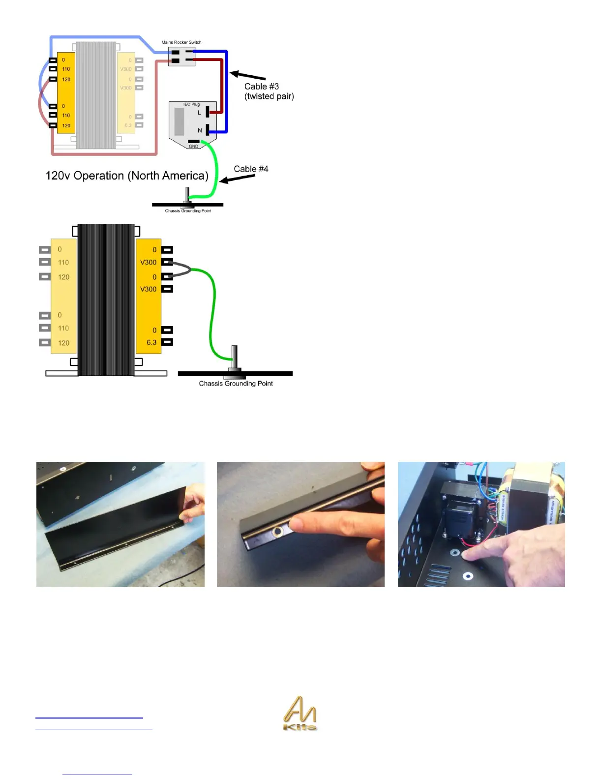
Add the twisted wire (Cable #3) and the ground wire (Cable
#4) as shown in the graphic opposite.
Let‟s add one final GROUND wire connection from the M4
screw in the chassis.
Take a piece of bare wire and solder it between the V300
and 0 terminals as shown opposite. Next, take a terminated
ground wire and strip the un-terminated end and solder it to
the short that you have just made. The other, terminated,
end connects to the chassis ground post.
Shield Positioning
I would like to explain where the shield fits at this stage – you won’t actually be installing this until the end of the
build but by then there will be a number of things inside the chassis.
Take a look at the shield provided and locate the hole underneath that has no paint on it – this will match up with a hole
on the chassis that is also unpainted in order to ensure a good grounding of the SHIELD when in stalled in the chassis.