power source. An indicator pin shows the selected input voltage in one
of the four holes in the cover (see Figure 4).
To change the input voltage, refer to and proceed as follows:
1. Remove the AC power cord from the AC Mains Connector.
2. Open the cover, using a small blade screwdriver or similar tool. Set
aside the cover/fuse block assembly.
3. Pull the voltage selector card straight out of the housing, using the
indicator pin.
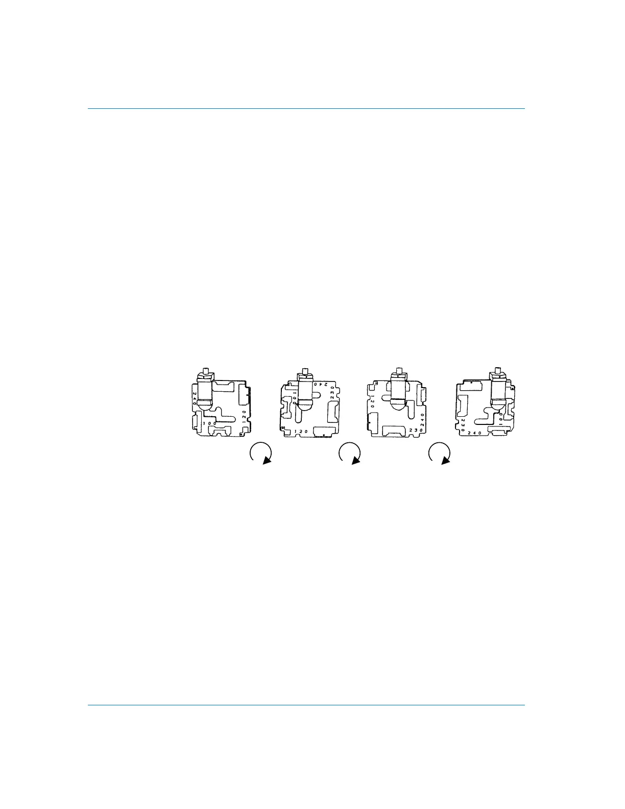
4. Orient the selector card so that the desired input voltage is readable
at the bottom (see Figure 5). Then orient the indicator pin to point
up when the desired voltage is readable at the bottom, with the
indicator pin assembly seated in the notch on the board edge.
5. Insert the voltage selector card into the housing with the printed
side of the card facing toward the connector, and the edge
indicating the desired voltage first.
6. Confirm that the correct fuse is installed for the intended input
voltage (refer to fuse ratings marked on the rear panel or in the
manual). If necessary, change the fuse type as described in the
following section.
7. Replace the cover and verify that the indicator pin shows the
desired voltage.
Primary Power Considerations Installation
Page 12 DCX-127 Multifunction Module User’s Guide
100 V 120 V 230 V 240 V
90º
90º 90º
Figure 5. Voltage selector card positions