entered or the present value edited from the keyboard, followed by
pressing the
E key.
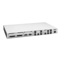
Operation Panel
DCX-127 Multifunction Module User’s Guide Page 23
Table 2. Digital I/O Connector Pin Assignments
Pin
Number
Function, Two’s
complement mode
Function,
BCD mode
1 Ground Ground
2 Bit 0 (LSB) LS digit, 1
3 Bit 1 LS digit, 2
4 Bit 2 LS digit, 4
5 Bit 3 LS digit, 8
6 Bit 4 5th digit, 1
7 Bit 5 5th digit, 2
8 Bit 6 5th digit, 4
9 Bit 7 5th digit, 8
10
Bit 8
4th digit, 1
11
Bit 9
4th digit, 2
12 Bit 10 4th digit, 4
13 Ground Ground
14 Bit 11 4th digit, 8
15 Bit 12 3rd digit, 1
16 Bit 13 3rd digit, 2
17 Bit 14 3rd digit, 4
18 Bit 15 3rd digit, 8
19 Bit 16 2nd digit, 1
20 Bit 17 2nd digit, 2
21 Bit 18 2nd digit, 4
22 Bit 19 2nd digit, 8
23 Bit 20 (LSB) MS digit, 1
24 Sign Sign