Version 6.0 23 March 2010
Installation Manual 2. Installing the Device
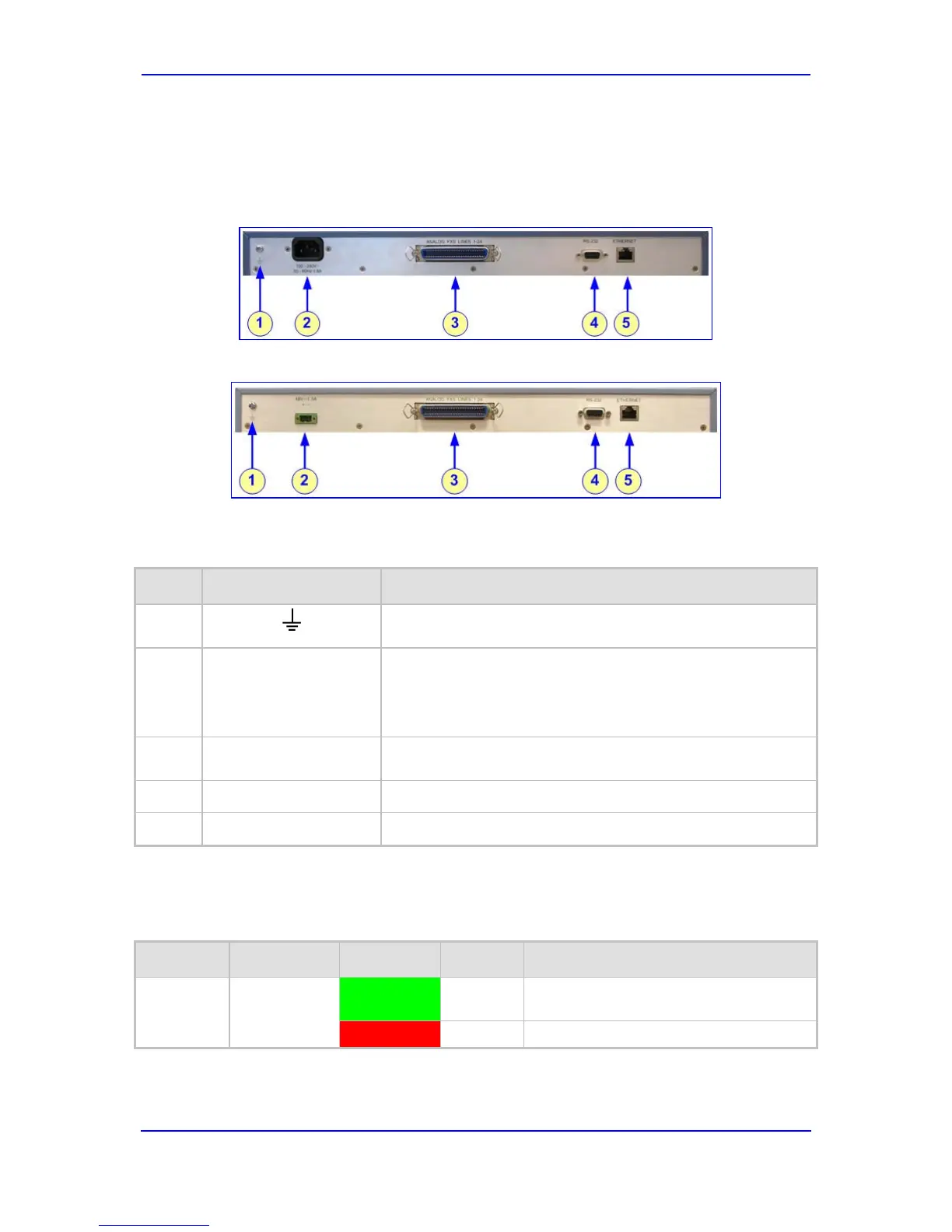
2.2.1.2 MP-124 Rear Panel
The device's rear panel (shown in the figure below) provides the ports for cabling the device
to the various interfaces.
Figure 2-14: MP-124 Rear Panel - AC Power Model
Figure 2-15: MP-124 Rear Panel - DC Power Model
The table below describes the MP-124 rear panel components.
Table 2-5: MP-124 Rear Panel Component Descriptions
Item # Label Component Description
1
Protective earthing screw (mandatory for all installations).
Accepts a 6-32 UNC screw.
2
100-250 V~
50 - 60 Hz 2A
- or -
The MP-124 can be ordered with one of the following power
configurations:
48V 1.3A
AC power:
provides an AC power supply socket
DC power:
3
provides a DC inlet for a DC terminal block
ANALOG FXS LINES
50-pin Telco connector for 1-24 analog lines.
1–24
4
9-pin RS-232 port.
RS-232
5
10/100Base-TX Ethernet RJ-45 port.
ETHERNET
The Ethernet LEDs are located within the RJ-45 socket. The table below describes these
LEDs.
Table 2-6: MP-124 Rear Panel Ethernet LEDs Description
Label Type Color State Function
Ethernet
Status
ETHERNET
Green On Valid 10/100Base-TX Ethernet
connection.
Red On Malfunction.
 Loading...