The special feature of AUMA redundancy II is its absolute, chronologically
synchronised response of the Profibus telegrams via both communication channels
with simultaneous monitoring of the passive channel on the basis of the received
DataEx request telegrams. This redundancy behaviour is imperatively required in
combination with DCS splitting a Profibus Stack to two redundant channels using a
voter.
The Behaviour Tx parameter can be used to influence the transmission of response
telegrams via the passive channel:
Tx active channel
Response telegrams are only sent via the active channel.
Tx both channels
Response telegrams are sent via both channels, the active and the passive channel.
4.4.2. Redundant behaviour according to Profibus DP-V2 redundancy (PNO guideline 2.212)
This redundancy type can be selected if the DCS supports Profibus DP-V2
redundancy according to Profibus DP guideline 2.212.
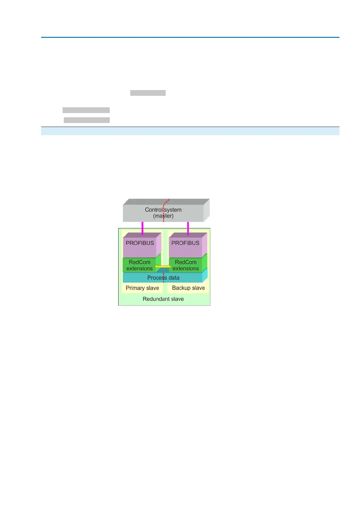
The physical structure of the redundant Profibus DP interfaces within the actuator
corresponds to the structure for AUMA redundancy; two independent, galvanically
isolated Profibus DP interfaces with an internal Redcom data channel for exchanging
the communication status.
Figure 3: Structure for DP-V2 redundancy according to guideline 2.212
The master generally uses parameter telegrams to determine which Profibus DP
communication channel is the primary channel and which is the backup channel.
The primary channel is used to operate the actuator, the backup channel can also
be used to establish a Profibus DP connection as an option; operation commands
of the backup channel will, however, be ignored by the actuator.
Feedback signals on the communication status of the two Profibus DP interfaces
and on received requests for changing the channels are performed by the extended
diagnostic (Red_Status, 3 bytes); not all DCS support this extended diagnostic
telegram.
Controls (DPM1 = master of class 1) can only write and read acyclic DP-V1 data via
the primary channel. Engineering stations (DPM2 = master of class 2) can use both
channels to read and write acyclic DP-V1 data (writing the same parameter via both
communication channels simultaneously is, however, not possible).
Details for change-over and behaviour are stipulated in PNO guideline 2.212.
If neither of the channels exchange process data with the controls or if both channels
receive Fail Safe telegrams (telegrams with the data length = 0) or Global Control
Clear (GC Clear) telegrams, the set failure behaviour or EMERGENCY behaviour
is started.
The redundant behaviour according to Profibus DP-V2 redundancy requires activation
of the Profibus DP-V2 functions.
43
Actuator controls
AC 01.2/ACExC 01.2 Profibus DP Description of the data interface