Do you have a question about the AUMA SAEx 14.6 and is the answer not in the manual?
Ensures compliance with regulations, understanding of safety instructions, and qualified personnel for safe operation.
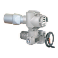
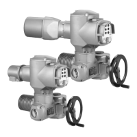
Definition and overview of AUMA multi-turn actuators, including motor, handwheel, and controls.
Describes information on approval plates for explosion-proof versions, including ATEX and IEC classifications.
Provides instructions and warnings for safe transport of the actuator, including suspended load precautions.
Step-by-step guide for mounting a multi-turn actuator with Output Drive Type A, including stem nut preparation.
Instructions for finish machining the stem nut for Output Drive Type A if supplied unbored or with pilot bore.
Step-by-step guide for mounting a multi-turn actuator with Output Drive Type B, including flange fit and torque specifications.
General safety warnings regarding electric shock and essential information for electrical connection procedures.
Procedure for connecting cables, including removing cover, inserting glands, fastening glands, stripping wires, and connecting cables.
Illustrates the correct method for connecting cables to the terminal carrier, including control and power terminals.
Shows the protective earth connections (M6 and M4) within the connection frame for safety.
Explains fieldbus connection for line topology, including terminal assignments and cable routing.
Explains the use of support terminals for solid fieldbus cables in line topology, with terminal assignment diagrams.
Explains fieldbus connection for loop topology, including automatic termination and information on redundant loops.
Shows how to close the terminal compartment, including cleaning faces, preserving joints, and fitting the cover.
Illustrates the KP and KPH electrical connections, showing Ex e and Ex d versions with screw-type terminals.
Explains manual operation for setting, commissioning, and valve operation using the handwheel.
Details motor operation, basic settings, and how to operate the actuator using local control push buttons.
Step-by-step guide to change the display language, including selecting the language and confirming the selection.
Explains the valve position indication (S0001) in percentage of travel, including bar graph and direction arrows.
Instructions on setting the type of seating (limit or torque) for end positions, emphasizing valve manufacturer consent.
Step-by-step guides for setting the CLOSED and OPEN end positions using limit switching elements.
Guides for setting intermediate positions for running directions CLOSE and OPEN using limit switching elements.
Instructions for setting the measuring range (0/4-20mA or 20-0/4mA) for the EWG transmitter.
Instructions for setting the potentiometer, including adjusting for end positions and fine-tuning the zero point.
Instructions for setting the measuring range for the RWG transmitter, including connecting an ammeter and adjusting potentiometers.
Lists common faults during commissioning, their causes, and remedies, including mechanical issues and measuring range problems.
Lists display indications for faults (S0001, S0005-S0011) and their descriptions/causes and remedies.
Details warnings and out-of-specification indications, their causes, and remedies, including configuration and external voltage issues.
Lists faults and failures with indications, descriptions/causes, and remedies, including configuration errors and phase faults.
Instructions for replacing fuses F1/F2 and testing/replacing fuses F3/F4, including fuse check methods.
Explains motor protection using PTC thermistors/thermoswitches and how to perform a proof test.
Instructions for disconnecting the actuator from the mains using KT/KM electrical connections, covering plug removal and fitting.
Instructions for disconnecting the actuator from the mains using KP/KPH and KES connections, covering plug removal and fitting.
Describes safety functions like local STOP and PVST, and monitoring functions for valve overload and motor temperature.
Provides a comprehensive table of tightening torques for various screw threads and strength classes.
| Brand | AUMA |
|---|---|
| Model | SAEx 14.6 |
| Category | Controller |
| Language | English |