Do you have a question about the AUMA SAExC Series and is the answer not in the manual?
Provides fundamental safety guidelines and standards for product operation.
Defines the intended industrial applications for multi-turn actuators.
Explains hazard warning signals (DANGER, WARNING, CAUTION, NOTICE) and their meanings.
Details references to other sections and explains common symbols used in the manual.
Describes the information found on the device's name plate for identification.
Provides a brief definition and overview of multi-turn actuators and controls.
Details safe procedures for transporting the actuator, including handling hovering loads.
Provides guidelines for proper storage to prevent corrosion and damage.
Describes the packaging materials used and recommendations for disposal.
Specifies that actuators can be operated in any mounting position.
Instructions for correctly attaching the handwheel to the actuator's change-over mechanism.
Guides on mounting the actuator to a valve or gearbox, covering different output drive types.
Details for mounting actuators with specific output drive types like B, B1-B4, and E.
Details for mounting actuators with output drive type A.
Procedure for machining the stem nut for output drive type A, if required.
Step-by-step instructions for mounting the actuator with output drive type A to a valve.
Information on optional accessories for actuator assembly.
Instructions for assembling the stem protection tube for rising valve stems.
Describes how to change the mounting position of local controls on the actuator.
Detailed steps for modifying the mounting position of local controls on the actuator.
General warnings and information regarding safe electrical connection procedures.
Instructions for connecting via plug/socket connectors with screw terminals.
Steps to open the terminal compartment for connecting cables.
Detailed guide for connecting cables to the terminals, including torque specifications.
Instructions for closing the terminal compartment after cable connections are made.
Instructions for connecting via plug/socket connectors with terminal blocks.
Steps to open the terminal compartment for connecting terminal blocks.
Guide for connecting cables to terminal blocks, including torque specifications.
Instructions for closing the terminal compartment after terminal block connections.
Optional accessories for electrical connections.
Description and use of the parking frame for disconnected plugs.
Information on the protection cover for the plug compartment.
Details on making an external earth connection for the device.
How to operate the actuator manually for setting, commissioning, or in case of power failure.
Step-by-step guide to engage manual operation via the change-over mechanism.
Procedure for disengaging manual operation, which happens automatically when motor starts.
Instructions for operating the actuator using the motor after commissioning.
How to operate the actuator locally using the control unit's push buttons.
Instructions for operating the actuator remotely via control commands or setpoints.
Explanation of the colours and assignments of the indication lights on the local controls.
Description of the mechanical position indicator and its functions for valve position and running status.
How binary output contacts are used for feedback signals like collective fault and end positions.
Information on analogue position feedback signals using potentiometers or RWG.
Specifies required heat-up times for low temperature versions of the actuator controls.
Instructions on how to open the switch compartment for settings.
Procedure for setting the torque switches for overload protection of the valve.
Guide for setting the limit switches to record actuator travel and operate switches at preset positions.
Steps to set the limit switch for the CLOSED end position.
Steps to set the limit switch for the OPEN end position.
Instructions for setting intermediate position switches for each running direction.
Procedure to set an intermediate position for the CLOSE running direction.
Procedure to set an intermediate position for the OPEN running direction.
Guidance on performing a test run after all settings are completed.
Procedure to verify the correct direction of rotation for the actuator.
How to check if the limit switching has been set correctly.
Procedure for testing the optional PTC tripping device for motor protection.
Instructions for setting the potentiometer as a travel sensor for valve position.
Guide for setting the electronic position transmitter (RWG) to measure valve position.
Steps to set the mechanical position indicator for valve open/closed status.
Instructions for closing the switch compartment after settings.
Procedure to open the actuator controls for adjustment.
How to set the type of seating (limit or torque) via DIP switches.
Setting the actuator operation mode to push-to-run or self-retaining.
How to activate or deactivate the running indication via a DIP switch.
Enabling or disabling the torque fault signal via a DIP switch.
Configuration options for the positioner function.
Configuring input signal types for setpoint and actual value for the positioner.
Defining actuator reactions (fail-safe modes) upon loss of input signal.
Procedure for adjusting the actuator's end positions with a standard positioner.
Adjusting the sensitivity (dead band) of the positioner to prevent excessive starts.
Setting the dead time to prevent frequent operation changes and reduce starts.
How to use the EMERGENCY command input to move the actuator to a preset end position.
Instructions for closing the actuator controls compartment after adjustments.
Troubleshooting common faults encountered during the initial commissioning phase.
Information on locating and replacing fuses within the actuator controls.
Specific details on fuses located inside the actuator controls for power supply and motor protection.
How to address issues related to motor overheating and thermal monitoring faults.
Essential preventive measures for safe operation and routine servicing of the actuator.
Procedure for safely disconnecting the device from the mains for service purposes.
Guidelines for maintenance tasks, including lubrication intervals and seal replacement.
Information on environmentally sound disposal and recycling of actuator components.
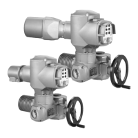
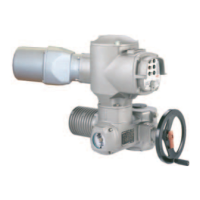
Detailed overview of the actuator's features, functions, and technical specifications.
Overview of the features and functions of the AUMA MATIC actuator controls.
Specifications for mounting position, enclosure protection, corrosion protection, and installation altitude.
Additional information including EU Directives relevant to the actuator.
List and diagrams of spare parts for specific multi-turn actuator models with screw terminals.
Spare parts list and diagrams for AUMA MATIC AMEXB 01.1 controls with screw terminals.
Spare parts list and diagrams for AUMA MATIC AMEXB 01.1 controls with terminal blocks.
Official declarations confirming compliance with EC directives and standards.
The EC type-examination certificate for equipment intended for potentially explosive atmospheres.
| Explosion protection | ATEX, IECEx |
|---|---|
| Ingress protection | IP66 |
| Ambient temperature | +70°C |
| Control signal | Profibus, Modbus |
| Protection class | Up to IP68 |
| Communication protocols | Profibus, Modbus, Foundation Fieldbus |
| Housing material | Aluminum |