Electric Rotary Actuators 2SA7
Technical Data
Page 20 Y070.304/EN
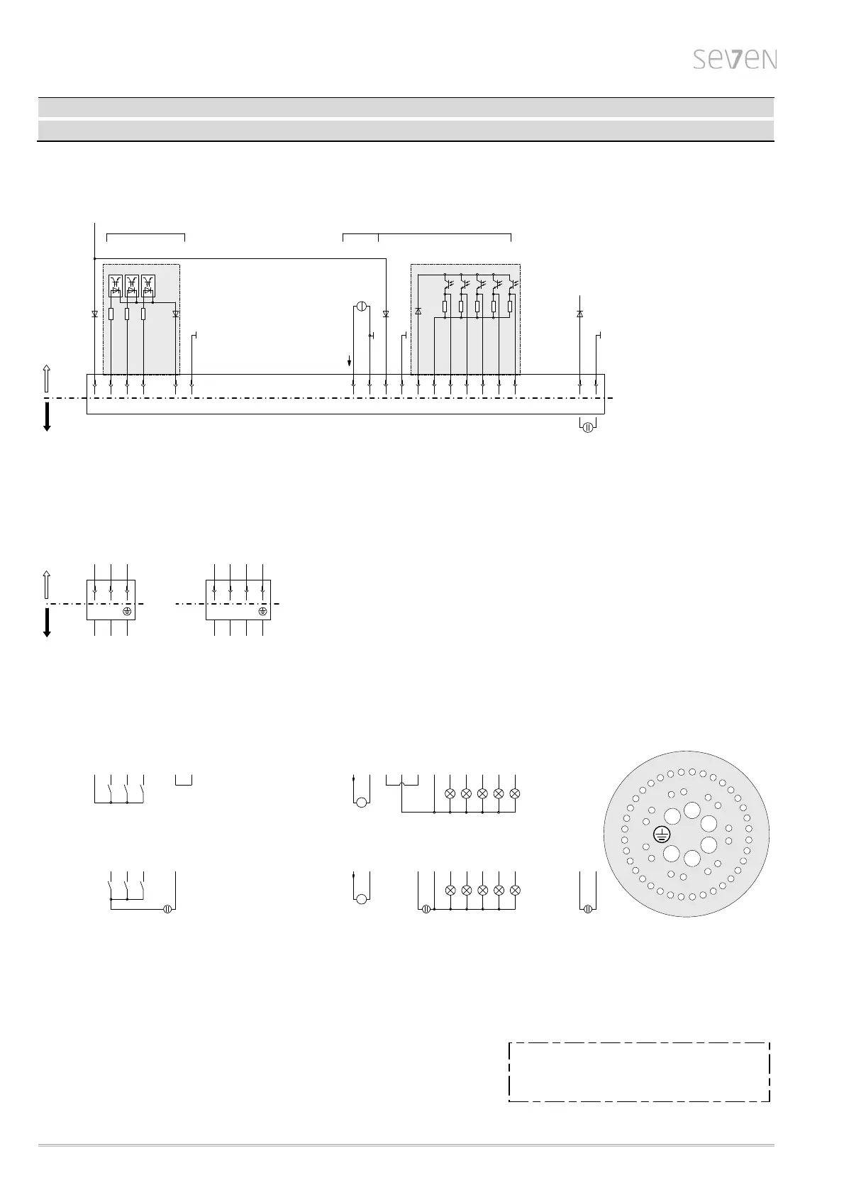
Wiring diagram ECOTRON Y070.243
Wire cross-section max.:
The control/feedback wire must be shielded!
Power supply
Control and feedback signals
6 mm
2
2.5 mm
2
-
-
1) galvanically isolated areas: can be supplied from different sources with 24/48V DC
2) auxiliary 24V DC supply for electronics unit (if required)
(In case of mains failure both actual position value and actuator status (binary outputs 1-5) will continued to be signalled.
Communication via COM-SIPOS – changes of parameters resp. download of actuator data – is possible.)
Plug assignment XK
4
2
4
1
4
0
2
8
2
9
3
0
3
1
32
3
3
3
4
3
5
1
2
3
4
5
6
7
8
9
2
7
2
6
2
5
2
4
23
2
2
2
1
2
0
1
9
1
8
1
7
1
6
1
5
14
1
3
1
2
1
1
1
0
4
3
4
4
4
5
4
6
4
7
5
0
3
7
3
8
3
9
U1
U2
V1
V2
W1
W2
4
8
4
9
3
6
23
Wiring example II: „external 24/48V DC supplies“
(in this example all galvanically isolated areas are supplied externally from different
24/48V DC power sources)
5
U
1
+
-
(
D
C
)
4 3816 17 2321 2219 20
U
2
+
-
(
D
C
)
(
2
4
V
D
C
)
2)
39
+
-
U
3
Wiring example I: „internal 24V DC supply“
(here all inputs and outputs are supplied internally from the electronics unit with 24V DC)
Customer connection - wiring examples:
1234 2321 2219 201715 16185 6
Connection control and feedback signals
Inputs
max. 125 mA
2)
1)
Outputs
binary
24/48V
binary
24/48V
+
-
24V DC
38 39
P24 ext.
G24 ext.
XK
234 5
1)
CLOSE
OPEN
G-BI
STOP
19 2321 222016 17
Output 5
Output 4
Output 3
Output 2
Output 1
P-BO
G-BO
1 61815
P24 int.
G24 int.
P24 int.
G24 int.
Customer connection Actuator internal
Connection power supply
L2
L1
XK
L3
PE
XK
W1U1 V1
L3L1 L2 PE
380-460V AC /
190-200V AC
3 phase input1 phase input
N
L1
U2 V2
LN
PE
PE
220-230V AC /
110-115V AC
XKXK
Actuator internalCustomer connection
78
+
-
analog
4...20mA
AO1
A
A
78
78