Electric Rotary Actuators 2SA7
Technical Data
Page 14 Y070.304/EN
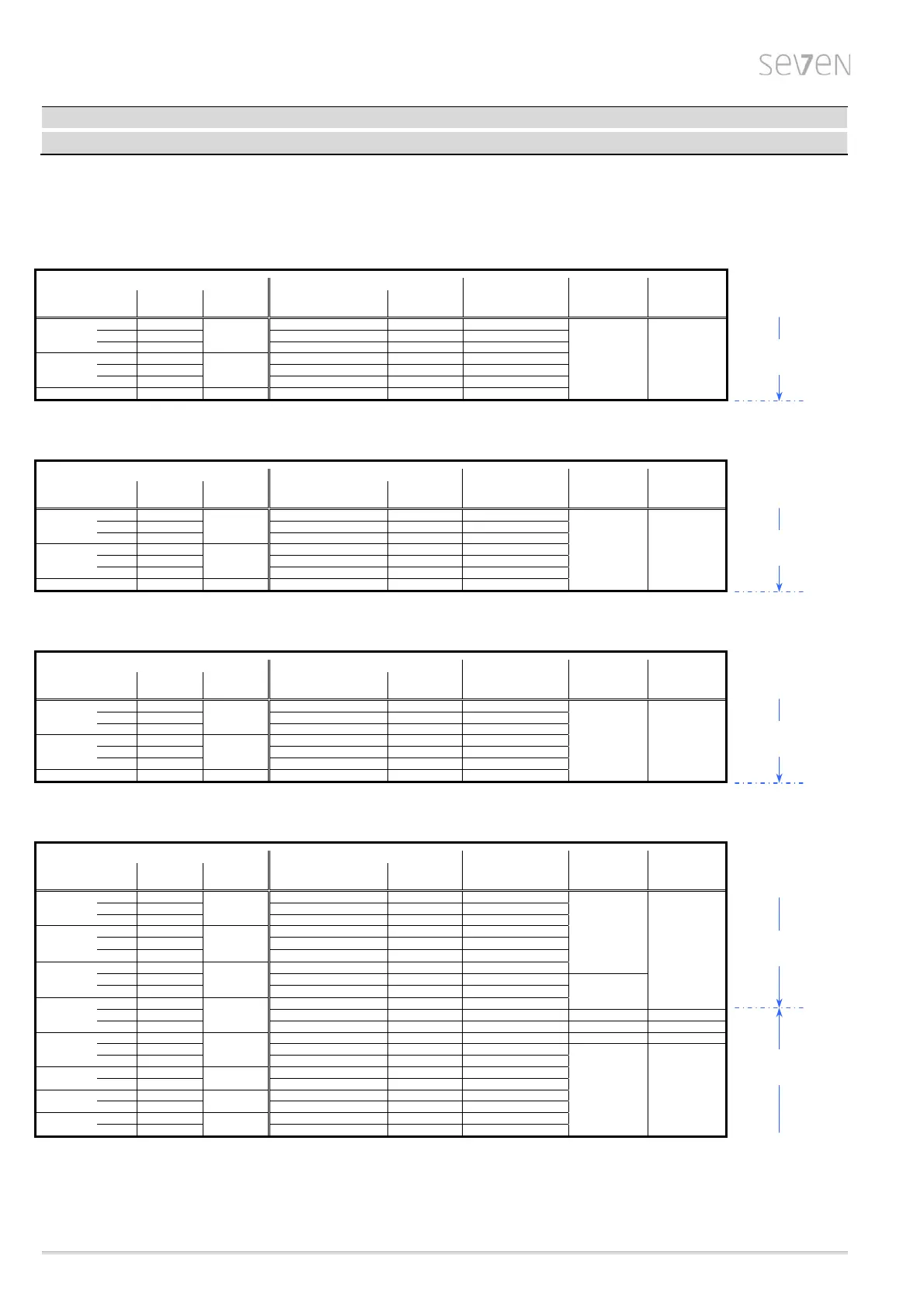
Electrical data – Power supply of ON-OFF duty (2SA70) and
Inching/positioning duty (2SA73)
Connection voltage U
N
1-phase, 110 – 115 V AC (40 – 70 Hz)
permissible voltage tolerance: -10% / +15%
Type Current (110 V)
Power P
N
Motor Fuse
2SA70..,
n
max.
T
C
max.
Nominal current I
N
≈ I
max.
power slow blowing
2SA73..
[rpm] [Nm] [A] [A] [kW] [kW] [A]
.....1.
-.CB 20
30
2.9 3.1 0.2
0.75 10
-.DB 40 3.1 3.8 0.2
-.EB 56 4.6 5.6 0.3
.....2.
-.CB 20
60
3.3 4.2 0.2
-.DB 40 4.8 6.5 0.3
-.EB 80 7.1 9.6 0.4
.....3. -.CB 20 112 6.1 7.9 0.4
Connection voltage U
N
1-phase, 220 – 230 V AC (40 – 70 Hz)
permissible voltage tolerance: -10% (-30%
1)
) / +15%
Type Current (230 V)
Power P
N
Motor Fuse
2SA70..,
n
max.
T
C
max.
Nominal current I
N
≈ I
max.
power slow blowing
2SA73..
[rpm] [Nm] [A] [A] [kW] [kW] [A]
.....1.
-.CD 40
30
1.7 2.1 0.2
0.75 10
-.DD 80 2.9 3.9 0.4
-.ED 112 2.7 3.6 0.4
.....2.
-.CD 40
60
2.3 3.1 0.3
-.DD 80 4.1 5.4 0.5
-.ED 160 6.0 10.0 0.7
.....3. -.CD 40 125 4.5 6.3 0.6
Connection voltage U
N
3-phase, 190 – 200 V AC (40 – 70 Hz)
permissible voltage tolerance: -10% (-30%
1)
) / +15%
Type Current (200 V)
Power P
N
Motor Fuse
2SA70..,
n
max.
T
C
max.
Nominal current I
N
≈ I
max.
power slow blowing
2SA73..
[rpm] [Nm] [A] [A] [kW] [kW] [A]
.....1.
-.CJ 40
30
1.2 1.5 0.2
0.75 6
-.DJ 80 2.1 2.8 0.4
-.EJ 112 2.0 2.6 0.4
.....2.
-.CJ 40
60
1.7 2.3 0.3
-.DJ 80 3.0 3.9 0.5
-.EJ 160 4.4 7.3 0.7
.....3. -.CJ 40 125 3.3 4.6 0.6
Connection voltage U
N
3-phase, 380 – 460 V AC (40 – 70 Hz)
permissible voltage tolerance: -10% (-30%
1)
) / +15%
Type Current (400 V)
Power P
N
Motor Fuse
2SA70..,
n
max.
T
C
max.
Nominal current I
N
≈ I
max.
power slow blowing
2SA73..
[rpm] [Nm] [A] [A] [kW] [kW] [A]
.....1.
-.CE 40
30
0.6 0.7 0.2
0.75
6
-.DE 80 1.0 1.2 0.4
-.EE 112 1.0 1.2 0.4
.....2.
-.CE 40
60
1.2 1.8 0.3
-.DE 80 1.4 1.8 0.5
-.EE 160 1.9 2.6 0.7
.....3.
-.CE 40
125
1.4 1.8 0.6
-.DE 80 2.4 3.1 1.0
1.50
-.EE 160 3.4 4.8 1.6
.....4.
-.CE 40
250
1.9 2.9 0.9
-.DE 80 4.1 5.4 1.8 3.00 10
-.EE 160 5.9 8.2 2.8 5.50 16
.....5.
-.CE 40
500
3.7 5.0 1.7 3.00 10
-.DE 80 7.5 10.0 3.7
5.50 16
-.EE 112 7.7 11.7 3.8
.....6.
-.CE 40
1000
5.6 10.8 2.6
-.DE 80 9.4 12.8 4.7
.....7.
-.BE 20
2000
7.5 10.0 3.7
-.CE 28 7.7 11.7 3.8
.....8.
-.AE 10
4000
5.6 10.8 2.6
-.BE 20 9.4 12.8 4.7
1) full torque for voltage fluctuations between –30 % and +15 %
(in case of undervoltage from U
N
–30% to –10%, operation may be performed at reduced output speed n)
2) lower voltage increases the current, higher voltage reduces the current
3) starting current I
A
≤ nominal current I
N
4) at 35% of the maximum torque T
C
max.
5) maximum current I
max.
is present for torque-dependent cut-off mode and for a running torque of 50% the maximum torque T
C
max.
small
electronics-
unit
small
electronics-
unit
small
electronics-
unit
big
electronics-
unit
small
electronics-
unit
 Loading...