Electric Rotary Actuators 2SA7
Technical Data
Page 4 Y070.304/EN
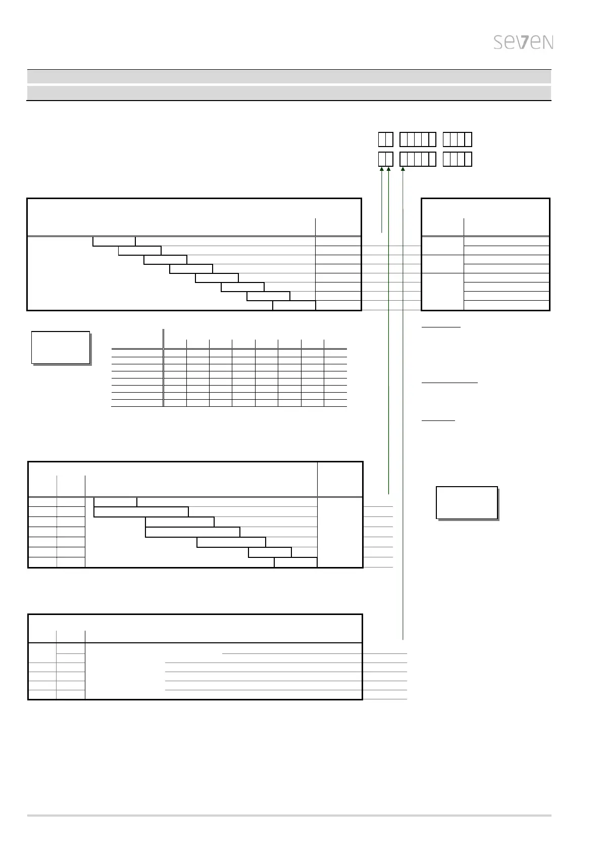
Mechanical data
1 2 3 4 5 6 7 - 8 9 10 11 12 13 14 15 16
ON-OFF dut
2SA70
- -
Inchin
/
ositionin
dut
2SA73
- -
Tripping torque
Adjustable tripping torque T
C
[Nm]
typical running torque > 50% max. torque T
C
max.
1)
Force for manual mode
2)
>> self-locking version (i = 40) <<
Weight
≈ [kg]
Crank length /
hand wheel dia.
at T
C
max.
9 – 30
19
1
60 mm
31 N
18 – 60 20
2
63 N
37
125
3)
34
3
90 mm
87 N
75 – 250 38
4
174 N
150 – 500 69
5
Ø 250 mm
125 N
300 – 1000 69
6
250 N
600 – 2000 136
7
132 N
1200 – 4000
136
8
263 N
Adjustable tripping torque in steps of 10% from 30%-100% max. torque T
C
max.
Tripping torque
range [Nm]
Tripping torque setting at .. % of T
C
max.
[Nm]
30 % 40 % 50 % 60 % 70 % 80 % 90 % 100 %
9 - 30 9 12 15 18 21 24 27 30
18 - 60 18 24 30 36 42 48 54 60
-
3)
37 50 62 75 87 100 112 125
75 - 250 75 100 125 150 175 200 225 250
150 - 500 150 200 250 300 350 400 450 500
300 - 1000 300 400 500 600 700 800 900 1000
600 - 2000 600 800 1000 1200 1400 1600 1800 2000
1200 - 4000 1200 1600 2000 2400 2800 3200 3600 4000
permitted tolerance: ± 10% of T
C
max.
Flange size
Flange size
for tripping torque [Nm]
Spindle
opening
[mm]
DIN ISO
5210
DIN
3210
F07
-
9-30
Dimensions for
A shaft (d6),
B1 shaft (d5)
and
C shaft (d11)
see page 8
0
F10 G0 9-30 18-60
7-125
1
F12 - 37-125 75-250
2
F14 G1/2 37-125 75-250 150-500
3
F16 G3 150-500 300-1000
4
F25 G4 600-2000
5
F30 G5 1200-4000
6
Output shaft design
Output shaft
form
DIN
4)
A ISO 5210 Output shaft with threaded bush
0
103
5)
+ acme screw thread Order-no. with „ - Z “ + Y18
B1 ISO 5210 bore with keyway
2
C 3338 claw coupling
3
B3 ISO 5210 bore with keyway
5
B2 / B4
6)
ISO 5210 bore with keyway Order-no. with H2Y
9
1) Exception: 35% for adjustment/setting to highest output speed for the types 2SA701 -.E, 2SA702.-.E, 2SA706.-.C, 2SA706.-.D, 2SA708.-.A and 2SA708.-.B resp.
2SA731 -.E, 2SA732.-.E, 2SA736.-.C, 2SA736.-.D, 2SA738.-.A and 2SA738.-.B and
25 % for 2SA706.-.D, 2SA736.-.D, 2SA708.-.B and 2SA738.-.B for separate mounting >10 m.
2) Non-self-locking actuators (refer to "Output speed“ column) have manual forces 30% higher.
3) Tripping torque range reduced to 37 – 112 Nm for 110 – 115 V connection voltage.
4) Special output shaft and output shaft design acc. to DIN 3210 on request.
5) Acme screw thread LH according to DIN 103, Part 2, thread nominal diameter as listed in Line 1, pitch according to preferred series.
The acme screw thread must be expressly stated, e.g. Tr 16 x 4 LH DIN 103!
6) The special bore must be stated, e.g. ø 26 with featherkey A8x7 DIN 6885!
30 % T
C
max.
is
default setting
Manual mode
>> Switchover only when drive is at standstill! <<
Switchover takes place by pressing in the hand
crank/hand wheel, motor stops operating automati-
cally.
Electrical operation restarts automatically after
releasing hand crank/hand wheel.
Direction of rotation: Turning hand crank/ hand
wheel clockwise results in clockwise rotation of
output shaft
(Exception: 2SA707.- and 2SA708.- resp.
2SA737.- and 2SA738.-).
Self-locking: The hand crank/hand wheel acts
directly on the motor shaft when turned by hand;
the self-locking function is thus retained for self-
locking actuators.
Dimensions to
flanges and output
shafts, see page 8
 Loading...