Electric Rotary Actuators 2SA7
Technical Data
Y070.304/EN Page 25
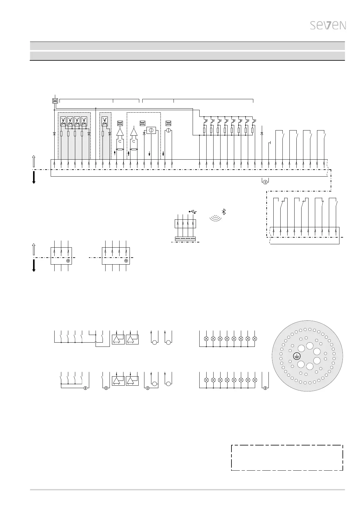
Wiring diagram PROFITRON with relay board Y070.248
Wire cross-section max.:
The control/feedback wire must be shielded!
Power supply
Control and feedback signals
6 mm
2
2.5 mm
2
-
-
1) galvanically isolated areas: can be supplied from different sources with 24/48V DC
2) auxiliary 24V DC supply for electronics unit (if required)
(In case of mains failure both actual position value and actuator status (binary outputs 1-8) will continued to be signalled.
Communication via COM-SIPOS – changes of parameters resp. download of actuator data – is possible.)
3) option
+
-
24V DC
2)
29 30 3432 3328 3531
46 4744 45
Output 8
Output 7
36 40 41 434237
Output 5
Output 6
Relay board
Output 1
Output 2
Output 3
Output 4
Plug assignment XK
4
2
4
1
4
0
2
8
2
9
3
0
3
1
32
3
3
3
4
3
5
1
2
3
4
5
6
7
8
9
2
7
2
6
2
5
2
4
2
3
2
2
2
1
2
0
1
9
1
8
1
7
1
6
1
5
14
1
3
1
2
1
1
1
0
4
3
4
4
4
5
4
6
4
7
5
0
3
7
3
8
3
9
U1
U2
V1
V2
W1
W2
4
8
4
9
3
6
23
Wiring example II: „external 24/48V DC supplies“
(in this example all galvanically isolated areas are supplied externally from different
24/48V DC power sources)
5
U
1
(
D
C
)
4 27 3817 2321 2219 20 24 25 26
(
2
4
V
D
C
)
2)
39
+
-
+
-
U
5
Customer connection - wiring examples:
Wiring example I: „internal 24V DC supply“
(here all inputs and outputs are supplied internally from the electronics unit with 24V DC)
123427 2321 2219 20 24 25 26179105 6
Connection power supply
Standard A
(USB socket under
screw cap on the
electronics housing)
COM-SIPOS
2
1
4
3
D--D+ +
USB 2.0
Bluetooth
Connection control and feedback signals
Inputs
max. 125 mA
Outputs
binary
24V
analog
0/4...20mA
XK
1234 527 910 19 38 3923 24 2521 22 2620176
1) 1)
P24 gal.
CLOSE
OPEN
G-BI
STOP
Mode
G24 gal.
EMERGENCY +
EMERGENCY -
G24 gal.
P24 ext.
G24 ext.
Output 8
Output 7
Output 6
Output 5
Output 4
Output 3
Output 2
Output 1
Customer connection Actuator internal
12
5
0
AI1
3)
11
-
+
78
AO1
+
-
AI2
5048 49
AO2
-
3)
13 14
P24
+
-
5
0
+
analog
0/4...20mA
binary
24/48V
L2
L1
XK
L3
PE
XK
W1U1 V1
L3L1 L2 PE
380-460V AC /
190-200V AC
3 phase input1 phase input
N
L1
U2 V2
LN
PE
PE
220-230V AC /
110-115V AC
XKXK
Actuator internalCustomer connection
11 12
(
D
C
)
10
+
-
U
2
9 11 12 13 14
A
48 49 50
(
2
4
V
D
C
)
U
3
+
-
13 14
A
49 50 78
A
78
A