Electric Rotary Actuators 2SA7
Technical Data
Page 6 Y070.304/EN
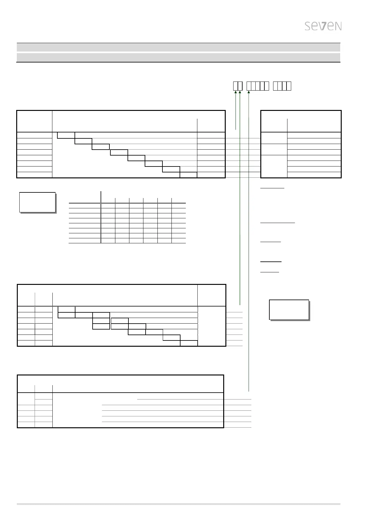
Mechanical data
1 2 3 4 5 6 7 - 8 9 10 11 12 13 14 15 16
Modulatin
dut
2SA75
- -
Tripping torque
Max.
act. torque
(modulating torque)
Adjustable tripping torque T
C
[Nm]
Force for manual mode
Weight
≈
[kg]
Crank length /
hand wheel dia.
at T
C
max.
15
10 – 20 19
1
60 mm
21 N
30 20 – 40 20
2
42 N
60 40 – 80 34
3
90 mm
56 N
125 87 – 175 38
4
122N
250 175 – 350 69
5
Ø 250 mm
88 N
500 350 - 700 69
6
175 N
1000 700 – 1400 136
7
92 N
2000 1400-2800 136
8
184 N
Adjustable tripping torque in steps of 10% from 50%-100% max. torque T
C
max.
Tripping torque
range [Nm]
Tripping torque setting at .. % of
T
C
max.
[Nm]
50 % 60 % 70 % 80 % 90 % 100 %
10 - 20
10 12
14 16 18 20
20 - 40
20 24
28 32 36 40
40 - 80
40 48
56 64 72 80
87 - 175
87 105
122 140 157 175
175 - 350
175 210
245 280 315 350
350 - 700
350 420
490 560 630 700
700 - 1400
700 840
980 1120 1260 1400
1400 - 2800
1400 1680
1960 2240 2520 2800
permitted tolerance: ± 10% of T
C
max.
Flange size
Flange size
for tripping torque [Nm]
Spindle
opening
[mm]
DIN ISO
5210
DIN
3210
F07
-
10-20
Dimensions for
A-shaft (d6),
B1-shaft (d5)
and
C-shaft (d11)
see page 8
0
F10 G0
10-20 20-40 40-80
1
F12 -
40-80
87-175
2
F14 G1/2
40-80
87-175
175-350
3
F16 G3
175-350
350-700
4
F25 G4
700-1400
5
F30 G5 1400-2800
6
Output shaft design
Output shaft
form
DIN
1)
A ISO 5210 Output shaft with threaded bush
0
103
2)
+ acme screw thread Order-no. with „ - Z “ + Y18
B1 ISO 5210 bore with keyway
2
C 3338 claw coupling
3
B3 ISO 5210 bore with keyway
5
B2 / B4
3)
ISO 5210 bore with keyway Order-no. with H2Y
9
1) Special output shaft and output shaft design acc. to DIN 3210 on request.
2) Acme screw thread LH according to DIN 103, Part 2, thread nominal diameter as listed in Line 1, pitch according to preferred series.
The acme screw thread must be expressly stated, e.g. Tr 16 x 4 LH DIN 103!
3) The special bore must be stated, e.g. ø 26 with featherkey A8x7 DIN 6885!
50 % T
C
max.
is
default setting
Self-locking
Rotary actuators for modulating duty are
self-locking actuators.
The gear ratio is i=40.
Dimensions to
flanges and output
shafts, see page 8
Manual mode
>> Switchover only when drive is at standstill! <<
Switchover takes place by pressing in the hand
crank/hand wheel, motor stops operating automati-
cally.
Electrical operation restarts automatically after
releasing hand crank/hand wheel.
Direction of rotation: Turning hand crank / hand
wheel clockwise results in clockwise rotation of
output shaft
(Exception: 2SA757.- and 2SA758.-).
Self-locking: The hand wheel acts directly on the
motor shaft when turned by hand; the self-locking
function is thus retained for self-locking actuators.