18. Setting the mechanical position indicator
.
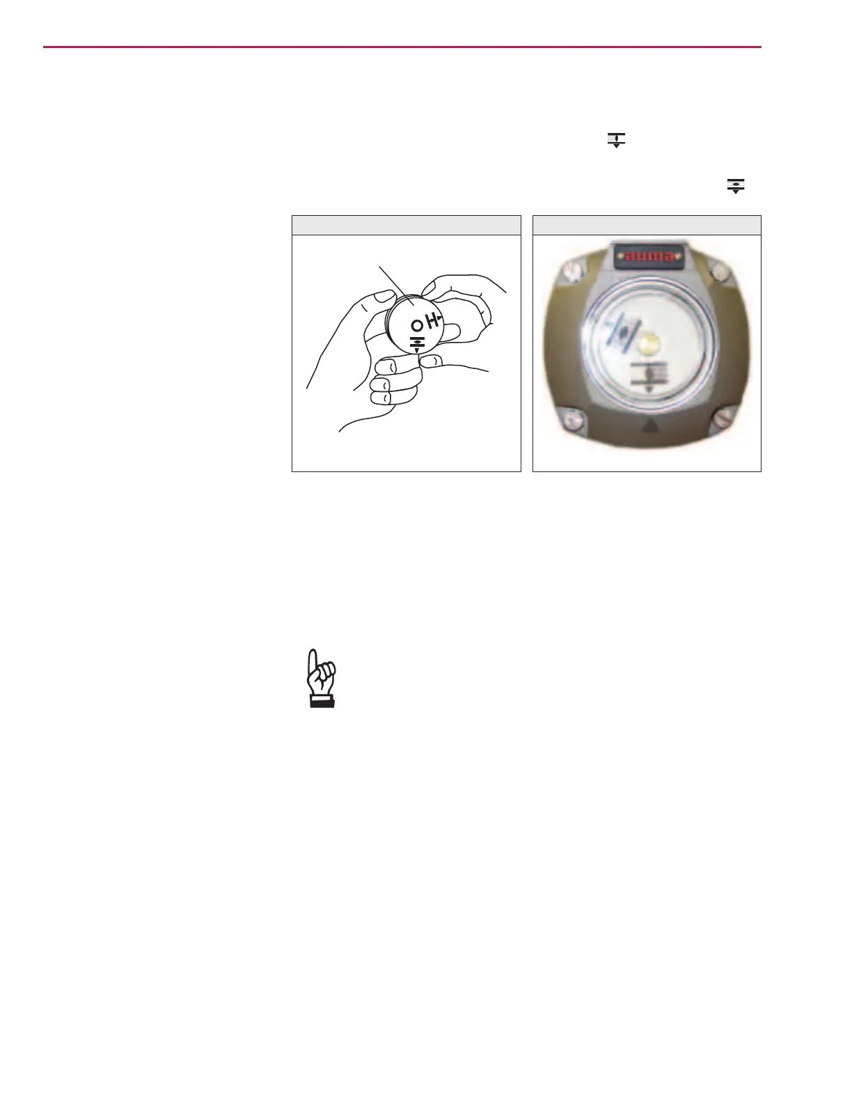
Place indicator disc on shaft.
.
Move valve to end position CLOSED.
.
Turn lower indicator disc (figure Q-1) until symbol CLOSED is in align
-
ment with the mark on the cover (figure Q-2).
.
Move actuator to end position OPEN.
.
Hold lower indicator disc in position and turn upper disc with symbol
OPEN until it is in alignment with the mark on the cover.
The indicator disc turns approx. 180° for a swing angle of 90°.
19. Closing the switch compartment
.
Clean sealing faces of housing and cover
.
Check whether O-ring is in good condition.
.
Apply a thin film of non-acidic grease to the sealing faces.
.
Replace cover on switch compartment and fasten bolts evenly crosswise.
Check the part-turn actuator for damage to paint finish. If
damage to paint-finish has occurred after mounting, it has to
be touched up to avoid corrosion.
Part-turn actuators SG 05.1 – SG 12.1 / SGR 05.1 – SGR 12.1
AUMA NORM Operation instructions
Figure Q-1
Indicator disc
Figure Q-2
Mark

 Loading...


