●
Coding:
-
DIN 4: High active (Triangle pointing in upward direction)
-
DIN 5: Low active (Triangle pointing in downward direction)
●
Signal state at input:
- DIN 4: Not active (triangle not filled in)
Low level = 0 V = No operation command in direction OPEN
- DIN 5: Active (triangle is black)
Low level = 0 V = EMERGENCY operation command is available
Diagnostic of digital outputs
For the digital outputs (DOUT), both coding and signal states are indicated at the
output by means of symbols.
Table 14: Symbol explanation
State output (output contact)Signal (indication)CodeSymbol
Low = 0 (output contact not operated)Not activeHigh active
High = 1 (output contact operated)ActiveHigh active
High = 1 (output contact operated)Not activeLow active
Low = 0 (output contact not operated)ActiveLow active
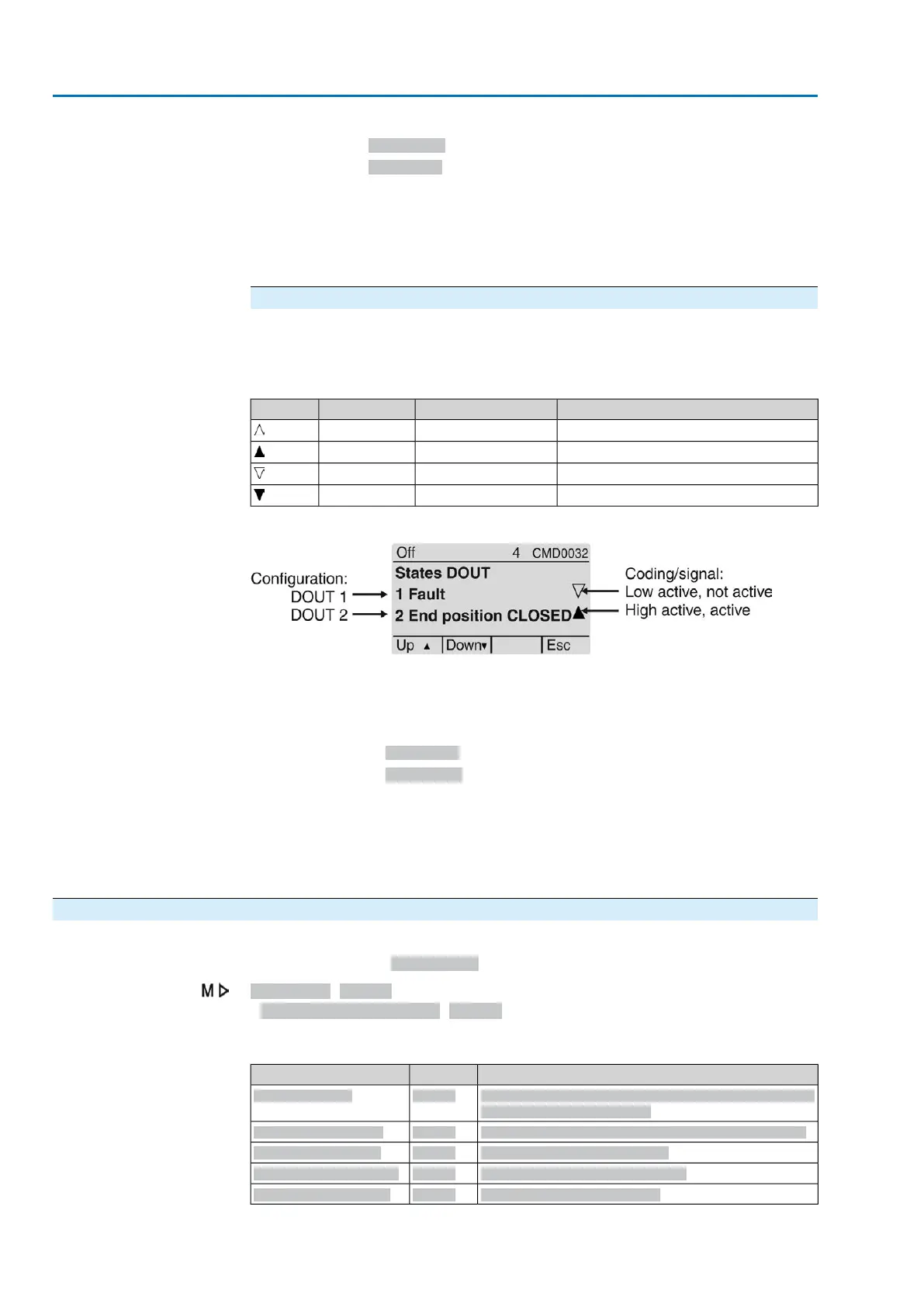
Figure 52: Example of DOUT 1 and DOUT 2
●
Configuration:
- DOUT 1: Indication: Fault has occurred.
- DOUT 2: Indication: End position CLOSED reached
●
Coding:
-
DOUT 1: Low active (Triangle pointing in downward direction)
-
DOUT 2: High active (Triangle pointing in upward direction)
●
Signal state at output:
- DOUT 1: Not active (triangle not filled in)
High level = +24 V DC = no indication (no fault available)
- DOUT 2: Active (triangle is black)
High level = +24 V DC= indication (end position CLOSED reached)
13.4. Diagnostic Position transmitter potentiometer
Menu is only visible if the actuator is equipped with potentiometer.
Required user level: Observer (1) or higher.
Diagnostic M0022
Position transm. potent. M0831
The following states can be checked via diagnostic:
SignificationMenu IDParameters
Low limit setting of potentiometer signal range (monitor-
ing the potentiometer span)
M0832Low limit Uspan
Current voltage level difference of the potentiometer.M0833Volt.level diff. potent.
Raw value end position OPENM0999Raw val. pos. OPEN
Raw value end position CLOSEDM1001Raw val. pos. CLOSED
Potentiometer raw value /mVM1005Potent. raw value /mV
106
Actuator controls
Diagnostics ACV 01.2/ACVExC 01.2

 Loading...