39
empty filter cartridge (this will ensure the
filter is not affected by the disinfectant/
sterilant solution).
3. Fill the water system with a disinfectant/
sterilant solution (check that the solution at
full strength appears at all taps/showers).
Allow to stand for the recommended
period of time.
4. Drain the system completely.
5. Thoroughly clean the outside of all taps/
connectors with a cloth soaked in the
disinfectant/sterilant.
6. Flush the system through with clean
drinking water until no traces of
disinfectant/sterilant can be detected at
any tap.
Suitable sterilising chemicals are available
from your motorhome dealer, accessory
shop, chemist or home-brew shops. It is not,
however, recommended to use bleach or
sodium metabisulphite.
Waste water system
(i) The waste water holding tank is
secured underneath the chassis of your
motorhome and is gravity fed.
(ii) In order to eliminate unpleasant odours as
much as possible, only smooth bore pipes
are used.
However, should the waste water tank be
overfilled, then the waste water will backfill the
drain pipes until it eventually appears in the
shower base. In order to prevent this, please
take note of part (iii).
(iii) The waste water gauge shows the level of
the tank in half increments, it is therefore,
recommended that the waste water tank is
checked on a daily basis, emptying when
required. This is done by opening the valve
located just beneath the side skirt on the
exterior of the Motorhome.
(iv) The waste tank may be drained by the
drain tap (grey) situated below the floor sill
of the van.
It should be emptied either directly, or via a
waste water container (not supplied) into a
designated waste water area.
PRESSURE SWITCH
The purpose of a pressure switch is to monitor
the pressure on the outlet side of the pump.
When a tap is closed, and the pump continues
to run, there is an increase of pressure in the
system, and when that pressure reaches a
pre-set limit, the pressure switch will turn the
pump off.
PRESSURE SWITCH ADJUSTMENT
Pressure Switch Adjustment, Truma/Flo-Jet
pump. (Normally Grey upper section with
White lower section/valve housing)
• AlloftheTruma/Flo-Jetpumpsusedby
Swift are pre-set at 25psi + / -3psi.
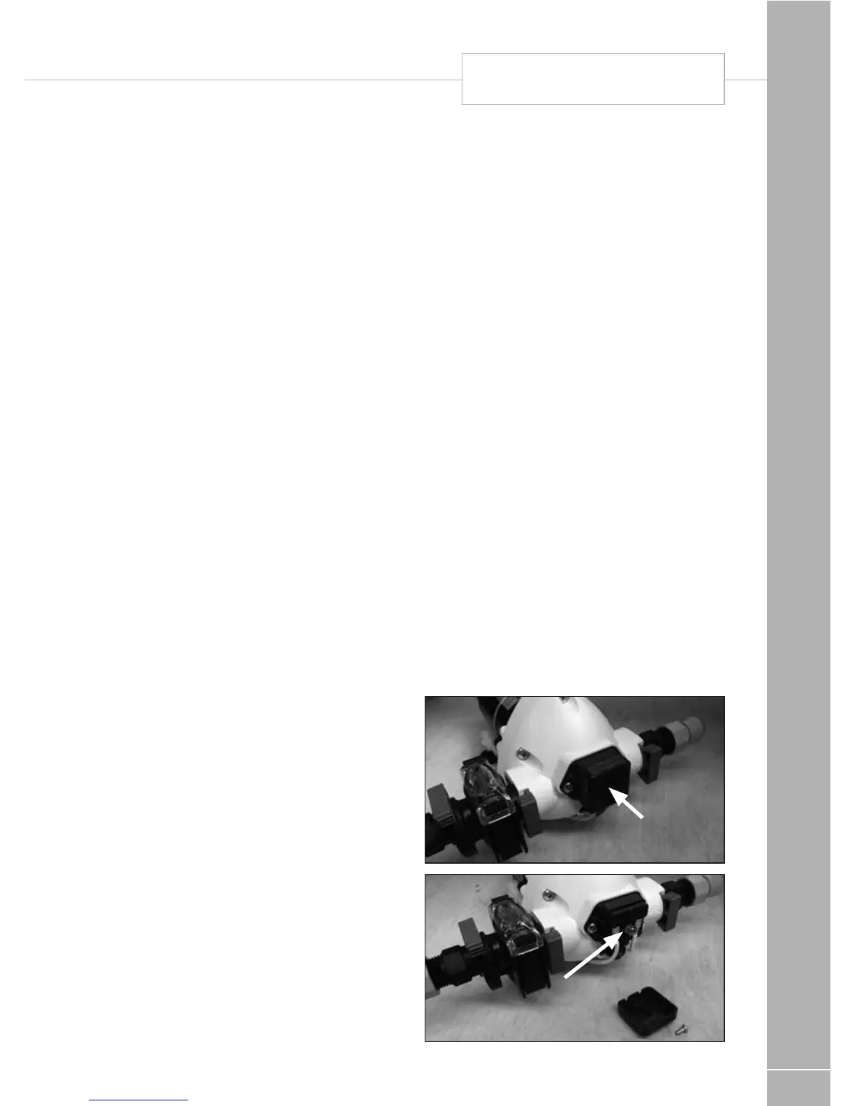
• Tofurtheradjustthepressureswitch
setting, a cover cap must be first be
removed from the end of the pump to
reveal a pressure adjusting screw, as
shown in the photos. A maximum of 1/4
turn clockwise or anti-clockwise, from the
factory setting, is advised. Turning the
screw clockwise 1/4 turn will increase the
pressure switch cut-out pressure, turning
the screw anti-clockwise will reduce the
pressure setting.
• Pleasenoteasecondscrewmounted
below the cover cap is set in position with
threadlock, this should not be disturbed.
Cover cap
Pressure switch
adjusting screw
pressure switch