41
water level sensor and cleaning
WATER LEVEL SENSOR
& CLEANING
Principle
The sensor, fitted to Swift Group motorhomes
are pre-fitted to water tanks, and link to the
control unit, via a pre-fitted wiring harness.
Two types of level sensor are used:
1. A series of float switches fitted through the
side of the tank at different levels which
provide a reading at the control unit.
2. A series of stainless steel studs in the side
of the tank, the conductivity of the water
between the studs providing a reading at
the control unit.
The sensors are 'digital', in that while the
conductivity (resistance) value can vary, the
fusebox will register any conductivity between
the reference stud and the other studs,
indicating water present.
Normally, even if the studs are dirty, and
providing the studs have not been bridged by
a foreign object, a circuit will still be delivered
back to the control unit and a water level
displayed. Similarly the float switches are either
open or closed indicating water whether water
is present or not.
Stud Sensor cleaning
The first step, in case of fault diagnosis, is
to clean the sensor studs. False water level
readings at the control unit can be caused by
calcium build-up or foreign objects within the
tank bridging the studs. (Especially with waste
tanks).
WARNING: Only use food safe plastic
mesh scourers, which are suitable for
domestic use, for cleaning the sensor studs.
1. Remove the studs from the tank
2. Check the studs for build up of
contamination
3. Use clean soapy water
4. Place scourer in water to dampen
5. Apply scourer to the sensor studs with
limited pressure
6. Rub sensor studs removing contamination
7. Swill sensor studs with fresh clean water
8. Replace sensor stud into tank, ensure they
are sealed.
PRESSURE SWITCH ADJUSTMENT
Pressure Switch Adjustment, Truma/Flo-Jet
pump. (Normally Grey upper section with
White lower section/valve housing)
• AlloftheTruma/Flo-Jetpumpsusedby
Swift are pre-set at 25psi + / -3psi.
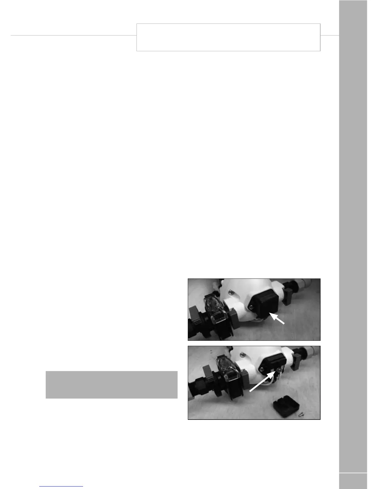
• Tofurtheradjustthepressureswitch
setting, a cover cap must be first be
removed from the end of the pump to
reveal a pressure adjusting screw, as
shown in the photos. A maximum of 1/4
turn clockwise or anti-clockwise, from the
factory setting, is advised. Turning the
screw clockwise 1/4 turn will increase the
pressure switch cut-out pressure, turning
the screw anti-clockwise will reduce the
pressure setting.
• Pleasenoteasecondscrewmounted
below the cover cap is set in position with
threadlock, this should not be disturbed.
Cover cap
Pressure switch
adjusting screw
The pump may have to be removed to gain
access to the adjusting screw. Drain the water
system before removing the pump.
To remove the pump pull the blue taps at right
angles to the pipe work and lift the pump out.