OptiFlex™ I/O Expanders (part no. FIO)
Automated Logic Proprietary and Confidential A Carrier Company. © 2022 Carrier.
All rights reserved.
17
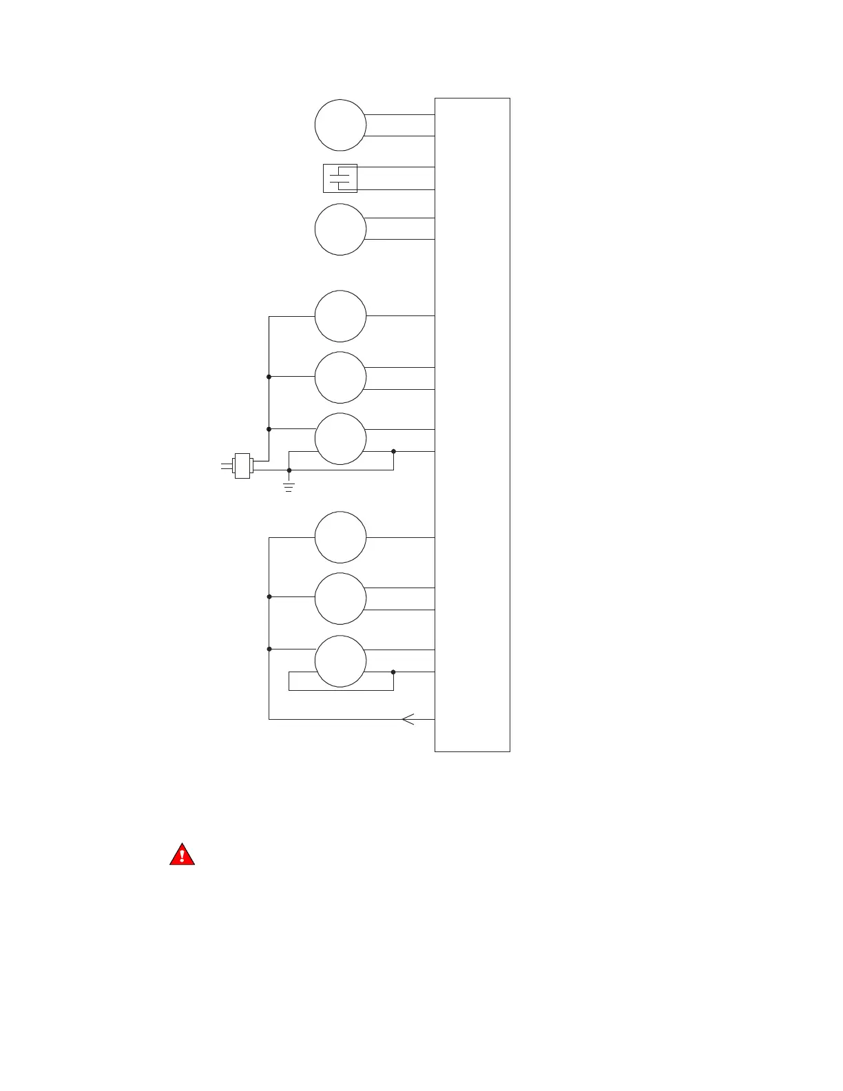
Dry
contact
Any input
-
-
-
-
-
-
-
-
-
External
24 Vdc
half-wave
power
supply
2 wire
3 wire
24 Vdc
connector
Out
V+
Gnd
+
Any input
+
Any input
+
Any input
+
Any input
+
Any input
+
Any input
+
Out
V+
Any input
+
10 kOhm
thermistor
1 kOhm
RTD
n/c
4 wire
2 wire
3 wire
4 wire
Out +
Out -
V+
Gnd
Any input
+
Out
V+
Gnd
Out
V+
n/c
Out +
Out -
V+
Gnd
0-5 Vdc,
0-10 Vdc,
or
4-20 mA
0-5 Vdc,
0-10 Vdc,
or
4-20 mA
0-5 Vdc,
0-10 Vdc,
or
4-20 mA
0-5 Vdc,
0-10 Vdc,
or
4-20 mA
0-5 Vdc,
0-10 Vdc,
or
4-20 mA
0-5 Vdc,
0-10 Vdc,
or
4-20 mA
NOTE For a loop-powered 4-20 mA sensor, wire the sensor's positive terminal to the + terminal on
the FIO expander's
24 Vdc connector. Wire the sensor's negative terminal to an input's + terminal.
4 Connect binary and analog output wiring to the UO screw terminals on the FIO expander and to the
controlled device. Connect the ground wire to the UO's – terminal.
WARNING Do not apply voltage to any output whose DIP switch is set to Analog.
 Loading...