rs (part no. FIO)
Automated Logic Proprietary and Confidential A Carrier Company. © 2022 Carrier.
All rights reserved.
18
Any UO
24 Vac/Vdc
+
+
–
–
Gnd
0-1 0 V
0-1 0 V
0-20 mA
0-20 mA
Hot
Hot
Gnd
4-wire
3-wire
+
Any UO
+
–
Hot
3-wire
+
Any UO
+
Coil: 24 Vac/Vdc, 1 A max.
Any UO
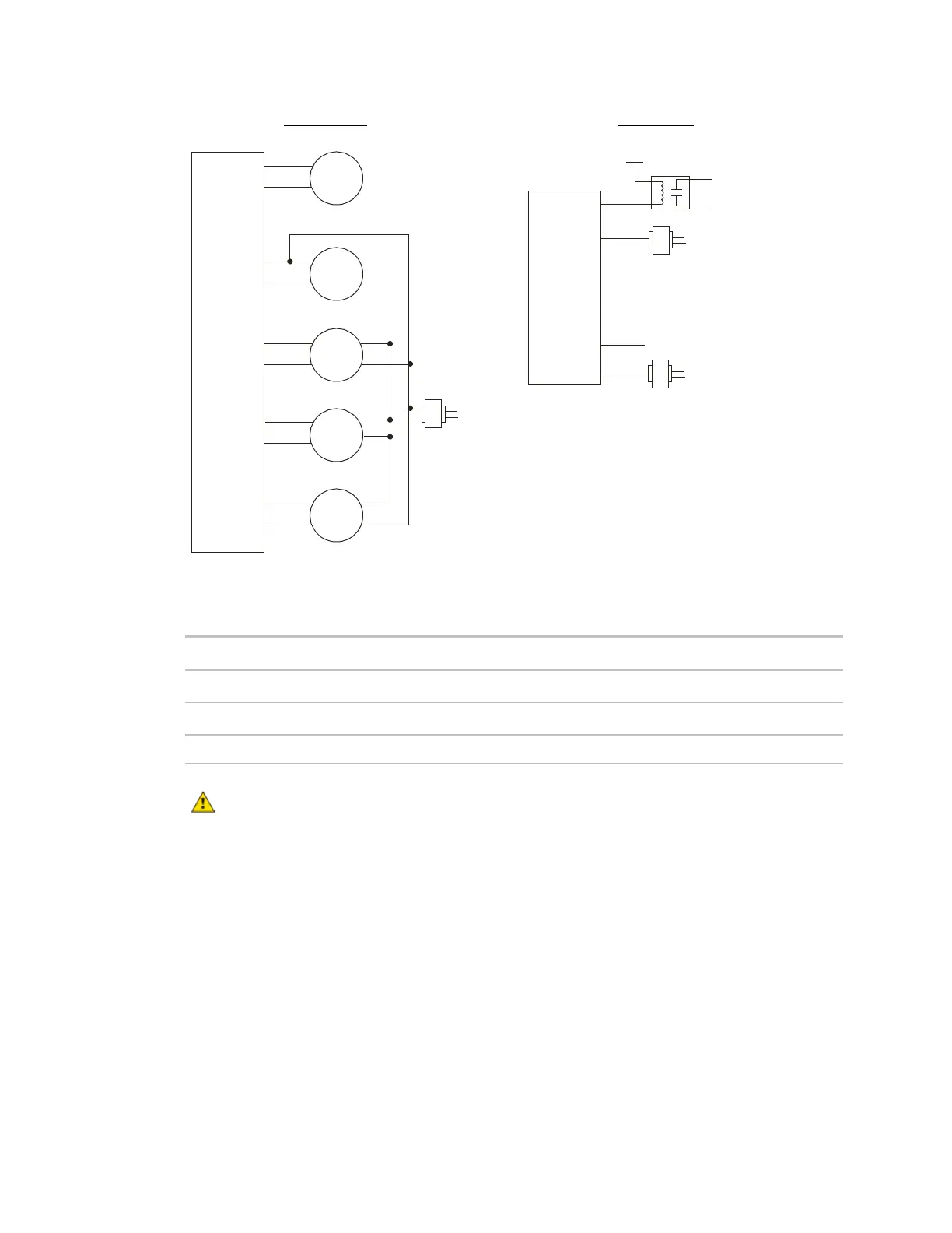
Analog outputs Binary outputs
-
-
-
-
-
+
+
–
Hot
Gnd
4-wire
Any UO
+
+
–
0-1 0 V
2-wire
Any UO
24 Vac/Vdc
+
Any UO
-
-
+
Gnd
24 Vac/Vdc
To external device
24 Vac/Vdc, 1A max.
5 Set each output's two DIP switches to the appropriate settings for the type of device wired to the
output.
Set bottom DIP switch to...
Analog 0-20 mA Up Up
Analog 0-10 Vdc Up Down
Binary Down N/A
CAUTION Outputs are set to Binary in the factory. To avoid damage to the expander, use a
voltmeter to verify there is no voltage on the + and – terminals before setting the DIP switch to
Analog.
6 Turn on the FIO expander's power.
See Troubleshooting inputs and outputs (page 24).
 Loading...