i–1
A
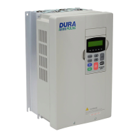
AC Drive
Cover: 1–6
Dimensions: 2–4
External Parts and Labels: 1–6
Heat Sink Fins: 1–6
Input Mode Switch (Sink/Source): 1–6
Introduction to DuraPulse GS3 AC drive:
1–3
Keypad: 1–6
Model Number Explanation: 1–5
Mounting Screw Holes: 1–6
Nameplate Information: 1–5
Nameplate Label: 1–6
Purpose of AC drives: 1–3
Selecting the Proper Drive Rating: 1–3
Serial Communication Port: 1–6
Specifications: 1–7
Terminal Diagrams: 2–13
Terminals - braking: 1–6
Terminals - control: 1–6
Terminals - power: 1–6
Ventilation Slots: 1–6
Accessories: 2–23, A–1a
Braking Resistors: A–20
Braking Units: A–20
Configuration Cable: A–48
Configuration Software: A–47
EMI Input Filters: A–29
Ethernet Interface: A–45
External Accessories: 2–23
Fans, Cooling: A–51
Feedback Card: A–41
Fuses and Fuse Kits: A–38
Keypad Cables: A–48
Miscellaneous: A–48
Part Numbering: A–2
Reactors, Line: A–2
Remote Panel Adapter: A–49
RF Filter: A–37
Spare Keypad: A–48
AFD: 1–3
Air Flow and Minimum Clearances: 2–3
Ambient Conditions: 1–10, 2–2
Analog Input Parameter Setup Examples: 4–46
Auto Restart after Fault: 4–58
Auto-tune Procedure: 3–14
AVERTISSEMENT: w–2
B
Braking Resistor Dimensions: A–24
Braking Resistors: A–20
Braking Units: A–20
DURAPULSE AC Drive User Manual
1st Ed. Rev. D 05/2013
INDEX

 Loading...