Do you have a question about the AutomationDirect DURAPULSE Series and is the answer not in the manual?
Provides an overview of the manual's content, target audience, and available support.
Introduces AC drives, their purpose, and guidance on selecting the proper drive rating.
Details the meaning of characters within the AC drive model numbers.
Explains the data presented on the AC drive's nameplate.
Lists the items included in the AC drive packaging.
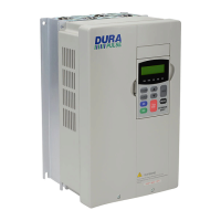
Identifies the physical components and labels on the AC drive's exterior.
Lists the technical specifications for the DURAPULSE AC drive series.
Specifies the environmental conditions required for safe AC drive operation.
Details the environmental requirements for storing AC drives before installation.
Provides essential guidelines for the proper and safe installation of the AC drive.
Specifies the required clearances and airflow for AC drive ventilation.
Illustrates the physical dimensions of various AC drive models.
Highlights critical safety precautions and essential guidelines before making connections.
Illustrates the terminal connections for different AC drive models.
Details the specifications for connecting the main power circuit to the AC drive.
Provides schematic diagrams for AC drive power wiring.
Lists and describes the terminals used for control circuits.
Illustrates wiring connections for sinking input configurations.
Illustrates wiring connections for sourcing input configurations.
Lists optional components that can be connected to the AC drive.
Describes the components of the digital keypad: LCD display, LEDs, and function keys.
Explains how to cycle through and interpret the AC drive's status messages.
Guides users on navigating parameter groups and settings for programming the drive.
Provides setup examples for common applications like constant and variable torque.
Details the procedure for motor auto-tuning in sensorless vector control modes.
Explains how to enable and use the function to store parameter settings.
Guides on transferring programmed parameter settings from the drive to the keypad.
Guides on transferring programmed parameter settings from the keypad to the drive.
Summarizes AC drive parameters and notes on firmware version dependencies.
Provides detailed explanations for all AC drive parameters.
Lists and explains parameters related to motor configuration and settings.
Explains parameters controlling acceleration and deceleration times and curves.
Details parameters for configuring V/Hz control curves.
Explains parameters for configuring digital inputs and outputs.
Lists and explains parameters for analog input and output signals.
Details parameters for preset speeds and jog functions.
Explains parameters for drive protection and fault handling.
Details parameters for configuring the Proportional-Integral-Derivative control loop.
Explains parameters for customizing the drive's display.
Lists parameters for configuring serial and network communications.
Explains parameters related to encoder feedback for precise speed control.
Provides a summary of all communication parameters with their ranges and defaults.
Lists the hexadecimal, Modbus decimal, and octal addresses for all parameters.
Lists the memory addresses used to monitor the AC drive's status and error codes.
Explains how to connect and communicate with DURAPULSE AC drives using AutomationDirect PLCs.
Provides examples of ladder logic programs for controlling DURAPULSE drives via Modbus RTU.
Provides examples of ladder logic programs for controlling DURAPULSE drives via Modbus RTU.
Offers a basic communication program for testing PLC to drive connectivity.
Provides guidelines for routine monthly and annual maintenance checks.
Details the procedure for recharging DC link capacitors on unused drives.
Covers fault messages and their corresponding corrective actions.
Lists common fault names, descriptions, and corrective actions.
Lists warning messages related to serial communication and keypad errors.
Explains the system used for part numbering accessories.
Details specifications and dimensions for LR and Legacy GS Series line reactors.
Lists specifications and dimensions for braking units and resistors.
Lists specifications and dimensions for EMI input filters.
Details RF filter specifications, dimensions, and wiring.
Lists fuse kits and replacement fuses with specifications.
Describes the GS3-FB feedback card, installation, and wiring.
Details specifications and connectivity for the Ethernet interface.
Describes ZIPLink cables for RS-485 Modbus RTU control.
Introduces the GSoft configuration software and its system requirements.
Lists configuration cables, spare keypads, and keypad cables.
Describes the remote panel adapter for keypad mounting.
Details communication distribution blocks for legacy GS Series drives.
Lists replacement cooling fans for DURAPULSE AC drives.
Lists compatible AutomationDirect PLCs and modules for use with DURAPULSE AC drives.
Shows typical connections between DURAPULSE AC drives and AutomationDirect PLCs.
Illustrates connections for CLICK PLC sinking DC output modules.
Illustrates connections for CLICK PLC sourcing DC output modules.
Illustrates connections for CLICK PLC sourcing analog current output modules.
Illustrates connections for CLICK PLC DC input modules.
Illustrates connections for DirectLOGIC sinking DC output modules.
Illustrates connections for DirectLOGIC sourcing DC output modules.
Illustrates connections for DirectLOGIC analog output modules.
Illustrates connections for DirectLOGIC PLC DC input modules.
Illustrates wiring diagrams for digital output terminals.
Illustrates wiring diagrams for relay contact output terminals.
| Output Current | Varies by model |
|---|---|
| Enclosure | NEMA 1 |
| Communication Interface | Modbus RTU |
| Protection Features | Overcurrent, Overvoltage, Undervoltage, Short Circuit |
| Operating Temperature | 0 to 40°C (32 to 104°F) |
| Storage Temperature | -40°F to 158°F (-40°C to 70°C) |
| Humidity | Less than 95% RH (non-condensing) |
| Power Rating | Varies by model |