K-27
(A)
Photo
electric
sensor
(B)
Fiber
optic
sensor
(C)
Door/Area
sensor
(D)
Proximity
sensor
(E)
Pressure
sensor
(F)
Rotary
encoder
(G)
Connector/
Socket
(H)
Temp.
controller
(I)
SSR/
Power
controller
(J)
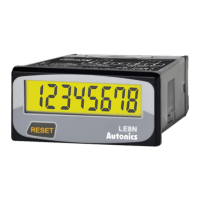
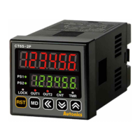
Counter
(K)
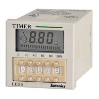
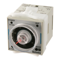
Timer
(L)
Panel
meter
(M)
Tacho/
Speed/ Pulse
meter
(N)
Display
unit
(O)
Sensor
controller
(P)
Switching
mode power
supply
(Q)
Stepper
motor&
Driver&Controller
(R)
Graphic/
Logic
panel
(S)
Field
network
device
(T)
Software
(U)
Other
LCD Timer(Touch Type)
[Fig.1]
Time Range
● Time range specications
● Time range selection method
※
Time range according to output operation mode
※
Time range owchart
Parameter Time range specication
s (9.999s) 0.010sec. to 9.999sec.
s (99.99s) 0.01sec. to 99.99sec.
s (999.9s) 0.1sec. to 999.9sec.
s (9999s) 1sec. to 9999sec.
m s (99m59s) 0m01sec. to 99min. 59sec.
m (999.9m) 0.1min. to 999.9min.
m (9999m) 1min. to 9999min.
h m (99h59m) 0h01min. to 99hour 59min.
h (99.99h) 0.01hour to 99.99hour
h (999.9h) 0.1hour to 999.9hour
h (9999h) 1hour to 9999hour
When
OND
,
ONd1
,
ONd2
,
INT
,
INt1
,
OFD
mode
1) In function setting mode, if it enter into time range mode, the characters will be
displayed as shown in the [Fig. 1].
2) Select the time range using
and key.
(Refer to time range owchart)
3) Press
key to complete the time range setting and the next mode.
4) If pressing key for 3 sec., it will return to Run mode.
※
When
FLK
,
FLk1
,
NFD
,
NFd1
,
S-D
,
TWN
,
TWn1
time range[
T!RG
,
T@RG
or
OfRG
,
OnRG
can be individually set.
※
The shaded parameter(
) is factory default.
-Time range[
tRNG
]
:
OND
,
ONd1
,
ONd2
,
INT
,
INt1
,
OFD
mode
-
tOFF
/
tON
time range[
OfRG
/
OnRG
]
:
FLK
,
FLk1
,
NFD
,
NFd1
mode
-
T1
/
T2
time range[
T!RG
/
T@RG
]
:
S-D
,
TWN
,
TWn1
mode
tOFF
time range
T1
time range
tON
time range
T2
time range
99.99s
999.9s 9999s 99m59s 999.9m
9.999s 9999h 999.9h 99.99h 99h59m
9999m
 Loading...