Page - 31
8.7.c Low Voltage Wiring
WARNING - Failure to heed the following may result in permanent injury or death.
l ELECTRICAL SHOCK HAZARD – Turn off the electrical power to unit before servicing.
Connecting the Cell Cable
1.
The cell cable connector is keyed and must be aligned to connect properly. Line up the cell cord and
plug into the cell cord connector located on the bottom right of the Pool Pilot
®
base plate.
2.
The other end of the cell cable is connected to two (2) of the cells electrical terminals. A red weather
plug is placed in the unused contact hole.
Connecting the Tri-sensor Cable
The Tri-sensor cable is 12’ long (3.6 m) and connects the Tri-sensor Assembly to the Pool Pilot
®
.
Connect the white 6-pin connector to the mating receptacle located on the base of the Pool
Pilot
®
.
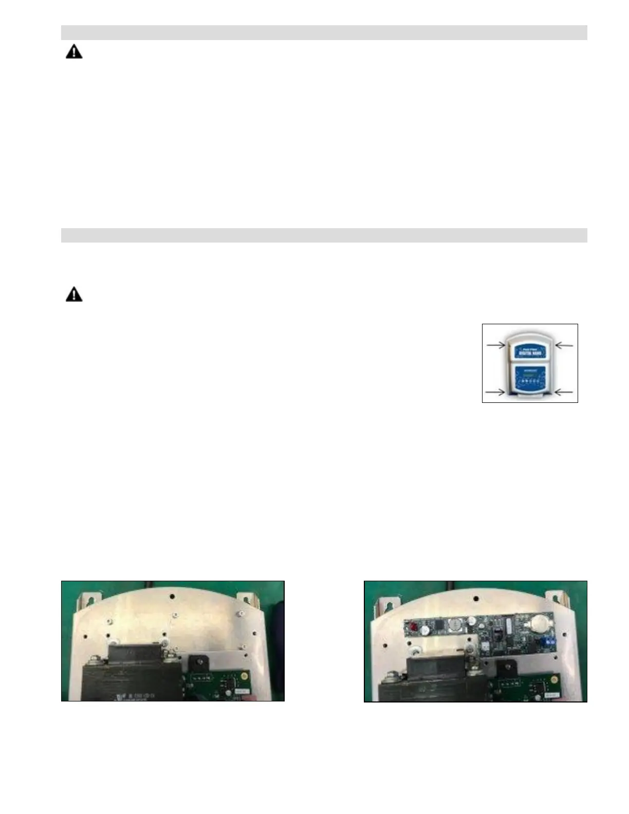
8.7.d Installing the Optional 863A Expansion Board
1.
Remove the cover by loosening the four recessed Phillips screws in the front corners of the cover.
2.
Carefully release the RJ11 modular plug at the cover end of the cable that attaches the 841-2C Display
Board. See Figure 20. Carefully set the cover aside.
WARNING - Failure to heed the following may result in permanent injury or death.
l RISK OF ELECTRICAL SHOCK - Disconnect all AC input power before you proceed with the next step.
Figure 17
3.
Affix the (5) 1/4" standoffs to the (5) Kept Nuts, provided with the STK0156 kit,
in the pre-drilled holes at top of the chassis. Do not over tighten.
4.
Place the 863A Expansion Board onto the standoffs and secure with (5) 1/8"
pan head screws. See Figure 19.
5.
Attach the flat ribbon cables (provided in the STK0156 Kit) to the 863A
Expansion Board in 2 places; JP1 on left and JP2 on right. Be sure the red line
is on left side of the ribbon. See Figure 21.
6.
Attach the flat ribbon cable from position JP1 on the 863A board, to the H1 position on the power
supply board. See Figure 21.
7.
Attach the second flat ribbon cable from position JP2 on 863A board, to the H4 position located on the
Interface Board. See Figure 21.
8.
Locate the terminal on the power supply board that has 4 male connectors. Remove the existing black
and white wires from these terminals only. They will be the top and bottom positions. See Figure 20.
9.
Using power cable ECA0348 provided in the STK0156 Kit, attach the multi-stack connectors as shown
in Figure 22 (top and bottom positions).
10.
Reattach the black and white wires, removed in step 8, to the multi-stack male terminals. Connections
will go to the upper and lower male terminals. See Figure 23.
11.
Attach the remaining ends from ECA0348 to the power terminals on the left side of 863A board. Note:
Black wire on top and White on the bottom. See Figure 24.
Figure 18
Figure 19