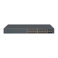
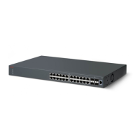
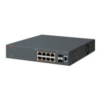
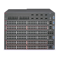
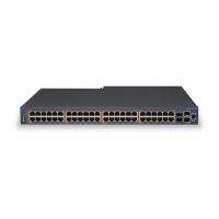
Switch Optional equipment Equipment
• M6 rack mounting screws (not shown) — Quantity: 4
Required tools
Phillips #2 screwdriver is required for attaching brackets to the switch.
Cable requirements
The following table describes the cables required for Avaya Ethernet Routing Switch 3500 Series.
Category 5E or higher specification cabling should be used for 1 Gbps/1000 Mbps operation.
Required Cable Description
Avaya RJ-45/DB-9 console cable 1.8m cable with DB-9 Female for terminal/PC on one
end and RJ-45 for device console port connectivity
on the other.
Avaya DB-9/USB integrated console cable 1.5m cable with USB Connector for PC and DB-9 for
device console port, also included USB Driver.
Stacking cables
Stacking cables are not included and must be ordered separately for Avaya Ethernet Routing Switch
3500 Series 24-port and 48-port models.
Order code Description
AL3518001-E6 46cm SFP direct connect stack cable
AL3518002-E6 1.5 meter SFP direct connect stack cable
AL3518003-E6 3 meter SFP direct connect stack cable
Switch installation
This section describes how to install the switch on a table or shelf, or in an equipment rack. The
installation procedure is different for ERS 3510GT / ERS 3510GT-PWR+ from the other switch
models in the series.
ERS 3510GT / ERS 3510GT-PWR+ can be installed on a table or shelf, or wall mounted. It can also
be installed in an equipment rack like the other switches in the ERS 3500 Series.
See the following procedures to install the switch:
• Installing ERS 3500 in an equipment rack on page 23
• Installing ERS 3510GT or ERS 3510GT-PWR+ on page 24
Installing the Avaya Ethernet Routing Switch 3500 Series
September 2016 Installing Avaya Ethernet Routing Switch 3500 Series 22
Comments on this document? infodev@avaya.com

 Loading...
