Table 8: Console port pin assignments
Connector Pin Number Signal
1 Ready to send (RTS) — optional,
can swap or link with pin 8
2 Data terminal ready (DTR) —
optional, can swap or link with pin
3 Transmit data (TXD) — mandatory
4 Carrier detect (DCD) — optional
5 Ground (GND) — mandatory
6 Receive data (RXD) — mandatory
7 Data set ready (DSR) — optional,
can swap or link with pin 1
8 Clear to send (CTS) — optional,
can swap or link with pin 1
LED state definitions
The figures and tables in the following sections describe the LEDs on the Avaya Ethernet Routing
Switch 3500 Series. The tables describe LED operation for a switch that finishes the power-on self-
test.
Warning:
Fiber optic equipment can emit laser or infrared light that can injure your eyes. Never look into
an optical fiber or connector port. Always assume that fiber-optic cables are connected to a light
source.
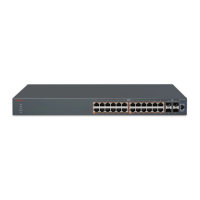
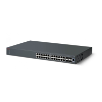
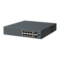
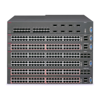
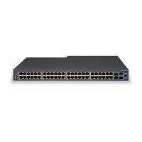
Switch front panel LED views
The front-panel PWR LEDs are lit when the device powers on.
The following figures illustrate the switch series front panel LED indicators.
LED state definitions
September 2016 Installing Avaya Ethernet Routing Switch 3500 Series 45
Comments on this document? infodev@avaya.com

 Loading...