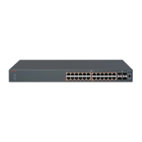
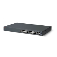
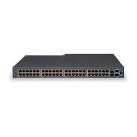
Installing a single ERS 3510GT or ERS 3510GT-PWR+ switch in an
equipment rack
About this task
Install the switch using the supplied brackets. The brackets secure the chassis and prevent it from
sliding around during vibration or when inserting or extracting transceivers.
Before you begin
Check for the following rack and bracket requirements:
• Ensure to provide the equivalent of one rack of vertical space for each switch in an E1A or 1EC
standard 19 inch (48.2 cm) and T1A 23 inch (58.5 cm) equipment rack.
• Appropriate rack space to accommodate 1U switch height (44 mm).
• Rack bolted to floor and braced if necessary.
• Rack must be grounded to the same grounding electrode used by the power service in the
area. The group path must be permanent and must not exceed 1 Ohm of resistance from the
rack to the grounding electrode.
• one 3510–Single Rack Mount Kit. For more information, see
Package contents on page 19.
Procedure
1. Ensure power is disconnected from the switch.
2. With the front of the ERS 3510GT or ERS 3510GT-PWR+ unit facing you, attach the small
bracket from the optional kit to the right side of the switch using the flathead screws
provided.
3. With the front of the ERS 3510GT or ERS 3510GT-PWR+ unit facing you, attach the long
bracket from the optional kit (see Figure that follows) to the left side of the switch using the
flathead screws provided.
Switch installation
September 2016 Installing Avaya Ethernet Routing Switch 3500 Series 27
Comments on this document? infodev@avaya.com

 Loading...