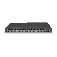
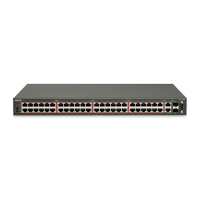
1. USB Port 4. Shared SFP ports and SFP+ ports. SFP ports can
support low speed 100FX SFP
2. Switch LEDs 5. Console Port
3. 10/100/1000 PoE+ ports (LEDs above ports)
Warning:
Fiber optic equipment can emit laser or infrared light that can injure your eyes. Never look into
an optical fiber or connector port. Always assume that fiber-optic cables are connected to a light
source. For a translation of this statement, see
Translations of safety messages on page 45.
Switch LED state indicators
The following table describes the main switch LED state indications provided by LED color and
fluctuation cues.
Table 8: Switch LED state indicators
Label Color and Status Description
PWR Green (solid) The switch is receiving power either from the primary or
secondary power supply.
Off The switch is not receiving power and not operating.
Status Green (solid) • During start-up: The power-on self-test (POST) is complete
and the switch is operating normally.
• After start-up: The switch is running the agent code
successfully.
Green (blinking) The switch is loading the agent software code.
Amber (solid) The switch encountered an error when running the diagnostic
software. (See note)
Amber (blinking) The switch is booting and running diagnostic software. Normal
activity during boot process. (See note)
Off The switch failed the power-on self-test (POST) or failed to load
the agent code.
Up / Down Green (solid) The switch formed a neighbor with the adjacent switch over
Stack up/down cables.
Green (blinking) The switch formed a partial neighbor with the adjacent switch
over Stack up/down cables. Check the switch logs.
Amber (solid) The switch detects Stack up/down cables are present and
connected to an adjacent switch, but adjacency did not
complete. Check the switch logs.
Off No Stack up/down connection is present, or the switch is in
stand-alone mode.
Table continues…
Check Light Emitting Diode on the switch
August 2016 Installing Avaya ERS 4800 Series 25
Comments on this document? infodev@avaya.com
 Loading...