Warning:
Disconnecting the AC power cord is the only way to turn off AC power to the switch. Always
connect the AC power cord in a quickly and safely accessible location in case of an emergency.
For a translation of this statement, see
Translations of safety messages on page 45.
Check Light Emitting Diode on the switch
The figures and tables in the following sections describe the LEDs on the switch. The tables
describe LED operation for a switch that finishes the power-on self-test.
Front panel LEDs
The following diagrams illustrate the components on the front panels of the switch:
For detailed explanations of the states indicated by each front panel LED type, see the following
sections:
• Switch LED state indicators on page 25
• Port LED state indicators on page 26
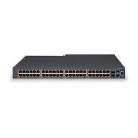
Figure 7: Avaya Ethernet Routing Switch 4826GTS
1. USB Port 4. Shared SFP ports and SFP+ ports. SFP ports can
support low speed 100FX SFP
2. Switch LEDs 5. Console Port
3. 10/100/1000 ports (LEDs above ports)
Check Light Emitting Diode on the switch
August 2016 Installing Avaya ERS 4800 Series 23
Comments on this document? infodev@avaya.com
 Loading...