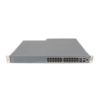
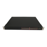
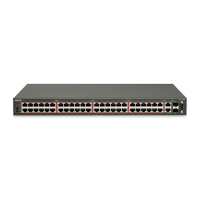
Figure 14: Redundant cascade stacking
1. Base Unit
2. Last Unit
3. Unit selector switch
4. Cascade Cable
In the example, the following occur:
• Unit 3 becomes nonoperational due to a unit failure, cable disconnection, or a loss of power.
• Units 2 and 4, directly upstream and downstream from Unit 3, sense the loss of link signals
from unit 3. The software directs all the data to traverse the remaining path.
• The Cascade Down LED for Unit 2 and the Cascade Up LED for Unit 4 turn amber to indicate
an error.
• The remaining stack units remain connected and continue to operate.
Replacing or adding a stack unit
To replace a failed stack unit or insert a new unit into a stack, perform this procedure.
Important:
Automatic Unit Replacement (AUR) for both configuration and software is enabled for all switch
platforms and software releases. This means that the agent code image, on a replacement unit,
is automatically upgraded or downgraded to match the software running on the stack. In
Stacking
August 2016 Installing Avaya ERS 4800 Series 39
Comments on this document? infodev@avaya.com

 Loading...


