VSP 7024XT 10GBase-T connection status
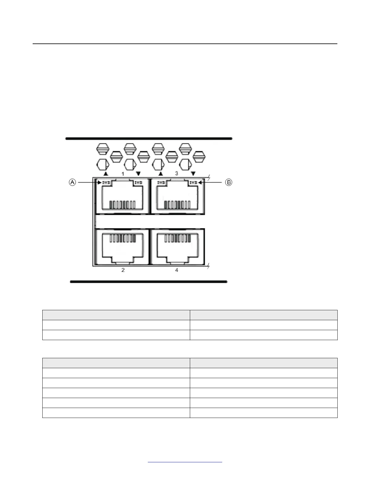
The VSP 7024XT switch includes 24 x 10GBase-T ports as primary client interfaces. Each pair of
10GBase-T ports has two LEDs to indicate connection speed and link activity. These LEDs are at
the top of the RJ-45 connector for the upper port of each pair. The LED on the left is assigned to the
upper port and the LED on the right is assigned to the lower port, as indicated by a triangle graphic
directly above each LED.
The following figure is a cutaway section of a VSP 7024XT switch that shows the 10GBase-T port
LED location.
Figure 26: VSP 7024XT 10GBase-T port status LEDs
Position LED assignment
A (Left side LED) Upper port LED
B (Right side LED) Lower port LED
The following table describes 10GBase-T port LED status.
LED state Description
OFF No Link
Slow Amber Blink Port Disabled
Solid Green 10GBaseT Link Active
Green Flashing Off 10 Gigabit traffic
Solid Amber 1GBaseT Link Active
Preparations for network connectivity
52 Installing Avaya VSP 7000 Series August 2014
Comments? infodev@avaya.com

 Loading...